5th,
First of all, I must say that the source of your 3rd harmonic problem was quite surprising! It must have been great to finaly identify and solve that, well done! (niot that I understand half of the other things that were investigated and tried...)
I found that a great surprise too. Somewhere in the back of my mind I knew that resistors had voltage ratings, but I always thought this was of a magnitude many times greater then anything I would ever (willingly) encounter. It was certainly a good moment when I figured it out though!
The first thing I notice, is that you have separate star-point returns for the rail decoupling capacitors, signal ground and loudspeaker returns.
My amplifier cards only have one return for all three, which is not according to what is defined as best practice according to some..
Well it's not just according to it's actually proven theory and proven practise. The decouplers inject all sorts of nasties into the ground that they feed into, if this enters and contaminates the sensitive input circuitry you can badly degrade the performance of an otherwise perfectly good amplifier. Now Douglas Self goes out of his way to exaggerate and show the worst case scenario for most of the distortion mechanisms he describes. In the real world you may not exactly degrade your performance by as much as he describes, but as it's often very easy to take the correct precautionary measures if you simply know about them in the first place.
I have allso read that a separate rail decoupling cap return should not be returend to the main starpoint, but to a point "upstream" of this, but it seems to work for you, especially considering the distortion figures you were finally able to obtain!
The rail decoupling should be returned to a point downstream of the signal ground return point. If it is placed up stream, it will 'flow' over the return point for the signal ground and risk contaminating it. At least that's how I've viewed it.
This is more important on a PCB with a ground plane, where the return path from the PCB to the star point is a wire located at one end of the PCB. At the far end of the PCB you've got a digital signal processing power house with all sorts of high frequency switching going on. At the end close to where the ground wire joins the PCB you've got a microphone pre amplifier. In this situation the dirty current returning from the DSP flows through the ground plane and over the mic preamp circuitry and as a result degrades the preamps performance. If the mic preamp had been placed at the far end of the PCB, and the DSP chip downstream of it, then the dirty current returning from the DSP would not flow over the mic preamp circuitry and all would be well.
Technically speaking you should be able to arrange the three returns (signal/load/decouplers) on a PCB so that they will have minimal interaction. Also none of this really has anything to do with ground loops that cause hum. You could simply measure the distortion performance of an amplifier card and see if it's within spec.
If I had signal ground disconnected from "power" ground. i.e. loudspeaker and decoupling cap return on my cards, and provided signal ground to the input and feedback shunt resistor ground points through the x-over board connection wire screens, and having the x-over board ground connected to the star point, I should in theory have the same grounding layout as you have?
This is of course assuming that you have the feedback shunt resistor and input ground connected directly to your signal ground with no "ground breaker resistors" etc..
I'll have to go over more of the thread and see exactly how you've got yours currently arranged as I need to go to bed!
The input ground on my amplifier PCBs has for all intents and purposes, the feedback shunt resistor and the resistor that sets the input impedance connected to it. I found that connecting the return for the constant current source didn't do anything to degrade the performance either, so that could be connected too if you want.
5th,
Very interresting your point about PCB layout Vs. ground returns.
To the degree I'm able to judge, it seems the designer of the Crescendo ME cards has had this in mind. Allso looking at the distortion measurements in the magazine article, they must have gotten something right! :
Good to hear that you allso run a groundbreaker resistor in your amplifier design.
Considering that both you and John use that and have working multi-channel amps, I think it is very obvious what I need to be doing over the next days! 🙂
Connecting the currnt source ground to the audio ground will be a bit more involved with my cards, so I wont pursue that.
But I'll connect all the grounds in the input network/filter to the Audio ground. By doing this, I can get away with cutting one PCB trace, jumper a 10 Ohm resistor across it, and then tack on that 18K input impedance adjustment resistor.
I'll do this on a card that is "easy" to get to today and see what it does for me, or, the amp rather.. 🙂
Hi,
how many mVac of noise does your DVM show when the input of the single powered Power Amp is shorted?
How many mVac of noise does your DVM show when the input of the single powered Power Amp is open?
Expect <0.05mVac for the shorted condition. Expect <1mVac for the open condition.
You might as well measure output offset while you are there.
You could measure all three Power Amps to see if they produce consistent results.
Now connect two Power Amps and measure the mVac of noise at the outputs of both powered Amps.
With shorted Input, about 0,5-1mV peak to peak ripple, and perhaps 0,4mV of general noise.
Open input, about 4mV ripple peak to peak.
Hmm.. just a question regarding the modification here.. JCX recommended that the 18K (12K) resistor that goes from R3 to signal ground, be connected to signal ground at the same point as the 10 Ohm resistor.
Looking at the PCB layout, there are two ways I can go about this.
If I want to connect the 18K resistor from the same point as the 10 Ohm resistor AND connect it exactly AT R3, I would need to add a bit of wire in order to reach across the board (about 3 cm perhaps)
My other alternative, is to still connect the 18k resistor at the same signal ground point as R3 and connect the other end somewhere along the trace leading from R3 to the base of T1 and T3 in dhe double differential input.
The first approach has the least impact with regards to the signal paths originally intended on the PCB, but carries the penalty of introducing that extra jumper-wire.
The second approach has the benefit of elliminating the need for additional jumper-wire, but introduces a component connection along a PCB trace where there was originally no connection.
Is either consideration of any practical relevance?
Hi, these peak to peak imply a scope measurement? What is the average voltage scaled to sinewave rms? Use your DMM set to 199.9mVac.With shorted Input, about 0,5-1mV peak to peak ripple, and perhaps 0,4mV of general noise.
Open input, about 4mV ripple peak to peak.
It looks like your noise measurements, both open and shorted, are about ten times too high, (+20dB).
Sort the power amplifier first. Then check the other power amplifiers.
Hi Andrew,
Yes these are scope measurements as per post #186.
I dont trust my multi-meter to resolve that low voltages accurately, I think the scope immages are much more revealing regarding what's going on.
I agree that this is much to high, hopefully the ground break resistor approach will help towards improving this, seems like the implementation of this is oen of the clear differences between my project and that of John and 5th.
If these scope traces are of a shorted input single power Power Amplifier then there is something wrong with the amp or PSU. It cannot be a grounding error. There is nothing else connected that can result in a non existant grounding error.I don't trust my multi-meter to resolve that low voltages accurately, ................. hopefully the ground break resistor approach will help towards improving this,
I trust my hand held DMM for all voltages, far more than I'd trust a scope trace.
They do two completely different jobs. One gives a measurement, the other gives a picture that varies with time.
Oh, as I believe I wrote in that post, the other amplifiers were connected to the PSU, and that explains most of the ripple on the shorted measurement. I did this measurement on a previous occasion with only the one amp connected to PSU, but didn't take a picture of the scope then. That trace showed only the noise floor and not the ripple.
Well, you probably have a better DVM than I have! If I get rich one day, I'll by a proper Fluke! 🙂
Well, you probably have a better DVM than I have! If I get rich one day, I'll by a proper Fluke! 🙂
Last edited:
I have a 25year old 2000 count DMM that reads down to 0.1mVac and 0.1mVdc.
I have an modern equivalent that reads to the same sensitivity. The old one cost about £20, the modern one cost £3.
They are both in tolerance for accuracy when compared to a Benchtop 50000count DMM. That cost me ~£50 incl post on Ebay.
I have an modern equivalent that reads to the same sensitivity. The old one cost about £20, the modern one cost £3.
They are both in tolerance for accuracy when compared to a Benchtop 50000count DMM. That cost me ~£50 incl post on Ebay.
Oh, well, perhaps I've underestimated the capability of my DMM, or I got one a cheap bad one in stead of a cheap good one! 😀
Annyway, just did the groundbreaker mod on one of the amplifier cards now.. and it looked good.. ripple could barely be distingusihed from noise on the scope, and when I hooked up the speaker there was no audible hum in the tweeter any longer. (this was the tweeter channel card)
Wow.. it would allmoust start to look like a solution has been found..😱
This has anyway given me agood feeling and confidence to go ahead with the other cards, this will be very interresting in deed..
The daylight falling through my kirtchen window is fading, and without it I do'n think I'll be able to doctor the other cards in the chassis, guess I'll have to leave that for tomorrow..
Hmmm.. or rather, fsssss..
Seems like the mod did a good job of removing hum from that one amplifier card I've implemented it on so far, but when connected to the x-over card, there's quite a bit of noise to be measured on the output. The scope shows a noise "curtain" of arround 1,5-2mV. This is audible 10-20 cm from the tweeter.
Again, it looks like this is something comming from the X-over card. But could there be something with the ground-breaker resistor mod that causes the card to generate noise? e.g the value of the resistors??
When I short the input to the amplifier card, the noise disappears and there is only a very weak ripple left (probably induced from the PSU or wiring)
Any comments or viewpoints on this would be welcome before I set about modifying the other amplifier cards! 🙂
Last edited:
Hi Elbert, good to hear that some progress has been made! Have you tried conecting a source? You might find the noise is not as bad with source connected (ie not a floating input). Of course if your source is noisy you might get the opposite 😉 Is it possible that the hum before was masking the other noise? ie it was there but what you were noticing was the hum?
Tony.
Tony.
Yes, it is in deed good to have some progress, things were getting a bit frustrating at one point! 🙂
I didn't measure the noise with a source connected, but shorting the input of the x-over card didn't change the noise, so I guess it will be the same with a source.
The noise was probably masked by the hum previously, at least to a certain degree, but on the scope it shows up more pronounced now.
I'm thinking perhaps it has something to do with the lowering of the amplifier input impedance after implementing the ground breaker resistors??
Anyway, as I need to get as closea s 20 cm to notice it, it won't be an issue as such, but if it is possible to reduce it further I would of course not mind! 🙂
But over to your amplifier.. do you know if it has any sort of ground-breaker resistor arrangement for the signal input ground??
the diff reciever mod requires/repays good resistor ratio matching, 1% resistors would be a good idea
the diff inputs should reject the noise between the XO and amp PS/Chassis/Safety Gnd - to the degree that the + and - input resistor divider ratios match
common impedance, some induced loop noise will still be measureable between the signal, output gnds but shouldn't appear in the amp ouputs (measure across the speaker output terminals)
JCX,
I was actually a bit uncertain about the criticality of the criticality of the resistor values..
The series resistors on the x-over cards were actually 220 oms, not 200, so from that I should ideally use a resistor value of 17617 Ohms. (which doesn't exist) The closest I got at the shop today was 18K. Could this deviation from optimum explain anything?
Having said that, I have bought some 232 Ohm resistors for replacing the 220 Ohm resistors, bringing the calculated value to 17923 Ohm, which is closer to the 18k resistor actually installed. Would that be good enough?
I bought some dual conductor signal wire with screen today, thinking it might be an improvement over the single conductor with screen I'm using at the moment.
I assume the two conductors are twisted inside the cable, and using these for signal/ ground connection, I will leave the screen connected in one end only so as not to create a loop in the cable. Don't know if this will make any difference?
depends how much common mode noise you need to reject - if you're off ~5% then you get ~ 20x reduction from the differential action
when you need high common mode rejection (>100x) you have to select or trim the resistor dividers - you can trim by adding a very large R in parallel to reduce the effective R value in one leg or include CMRR trim pots
coaxial with XO/signal gnd outer shield going to the "- input" of the amp board should be excellent - the impedance of the XO gnd/gnd lift R are so low there's no advantage to a electrostatic shield
coax has higher symmetry for rejecting magnetic field induced noise
the only "optimization" is to use heavier outer conductor - really cheap audio RCA "coax" may only have a dozen wires in the outer layer with irregular coverage, gaps, too much resistance
Last edited:
Well, according to my calculations, I'm off the ideal resistor value by about 0,5%, so that should be reasonably OK I guess. (this is when I have replaced the 220 ohm resistor with a 232 Om resistor, all the resistors I use are 1% tolerance)
The coax cable I use at the moment is not heavy duty microphone cable with super-fat screen, but certainly not of the dead-cheap type with only a few strands wrapped arround, so I guess it should be OK then.
This probably sounds terribly ignorant (which is pretty much the truth annyway) but what will the effects of increasing reducing the value of the 10 ohm "lift" resistor be?
I didn't measure the noise with a source connected, but shorting the input of the x-over card didn't change the noise, so I guess it will be the same with a source.
Yes a fair assumption! 🙂
But over to your amplifier.. do you know if it has any sort of ground-breaker resistor arrangement for the signal input ground??
Not as far as I can tell! Here is the schematic (I'm assuming you are talking about my playmaster which has the one completely quiet channel and one with hum)
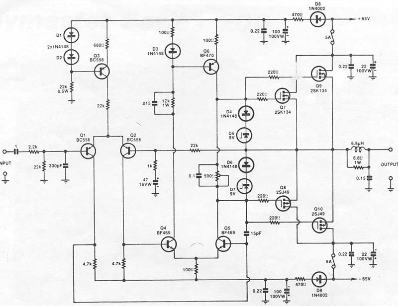
It's actually an integrated amp (though I am now bypassing the preamp and using it as a pure power amp). the board layout is below:

The chipamp is P2P wired and local stars for each channel connect back to the main star point which is on the powersupply board.
Tony.
Tony,
Yes I was thinking about your playmaster amp.
For the power-amp schematic, there doesn't seem to bee anything resembling any ground-breaker circuitry assocoated with the signal input or feedback loop..
Perhaps a modification to consider??
Yes I was thinking about your playmaster amp.
For the power-amp schematic, there doesn't seem to bee anything resembling any ground-breaker circuitry assocoated with the signal input or feedback loop..
Perhaps a modification to consider??
I have just noticed via a PM that the images I attached in my above post are not coming through. I will sort this out quickly.
Elbert there should not be a ground breaker, nor should there need to be one on the amplifier PCBs, between the input ground and the feedback shunt.
Elbert there should not be a ground breaker, nor should there need to be one on the amplifier PCBs, between the input ground and the feedback shunt.
- Status
- Not open for further replies.
- Home
- Amplifiers
- Power Supplies
- A Grounding challenge , please help..