")
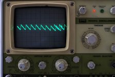
post267 pic 3 and post268 pic1, show a pulse above noise on the amp output. This looks like a charging pulse between transformer and smoothing capacitance via the rectifier. This should not appear on the output, nor should it appear on the supply rails of the amplifier. How is it getting to the output?
I wonder if input floating is allowing the rectifier loop to radiate air borne interference that the high impedance of an open input is able to pick up.
Does this "disappear" into the noise when the input is shorted and also when the input is terminated with 1k0?
Hi Andrew, sorry I missed the edit. I did do a measurement with input shorted, but I didn't post it because my shorting method was inadequate and I think contributed to noise pickup. I couldn't find any rca plugs that I could rig up with a short so I got a 10cm long lead with aligator clips and shorted it that way. I think the loop of wire though probably picked up noise (certainly the scope probe just held in the air picked up significant noise.
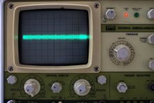
Anyway for what it is worth here is the pic with the shorted input, as you can see the pulses do disapear into the noise floor.
The first is the one with shorted input (albeit done in a dodgy way with the aligator clip lead) and second is with the input floating. As you can see the noise level with input shorted is higher, and I wasn't sure if that was masking the small artefacts that were showing when input was not shorted.
I didn't do the shorted measurement with the 1000uF supply unfortunately so I'm not going to be able to reproduce, now that both channels have been increased to 5700uF. Both the posted pics were with 5700uF on the supply.
I'll get some rca plugs so that I can properly test in future (I can't believe I didn't have any in the junk box!), and when I do I'll try with 1k as well as shorted.
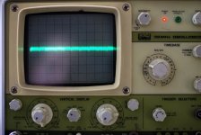
It's interesting that you say it looks like a charging pulse, and it shouldn't appear on the output or the supply rails, certainly the scope measurement of the supply ripple looks pretty clean (though admittedly I was going to measure both +ve and -ve rails and forgot to do the negative measurement, so I can't vouch for the negative rail!) I've re-added the +ve rail ripple scope pic as pic 3.
Tony.
Attachments
- Status
- This old topic is closed. If you want to reopen this topic, contact a moderator using the "Report Post" button.