Tony,
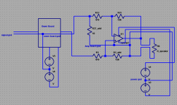
Your drawing represents the current configuration, and you are right,this creates a number of ground loops between the amplifiers. Which is bad.
Considering these loops together with the fact that the noisier third amp channel has the longest PSU connection wires, could explain some things.
Breaking these loops by disconnecting the screens in either end (x-over or amp side, didn't make any difference), and connecting the X-over to the starpoint, should be an implementation of correct star grounding theory, BUT it gives even more Noise. (pretty much the same level of noise on all channels)
This Seems to represent a dillemma I'm stuck within.
Using the first approach, which creates ground loops, give least noise, probably due to a shorter ground reference path (through screens).
The second solution that should elliminate ground-loop problems, seems to create some problems of its own... I suspect that the longer ground reference path, amp-card- star--x-over board, vould allow noise to be picked up..
If this is true, then I'm stuck either with induced ground noise or ground loop noise...
can the circuits be modified? - differential recievers for the amps, xover inputs can get around common impedance coupling
for diff pair input, Voltage feedback power amp circuits this is often only a couple of added resistors matching the feedback resistor ratio
slavish implementaitons of "star gnd" can also be a probelm - sometimes multi-level "clean"/"dirty" partiioning of gnds can be better - esp with the differential inputs on modules rejecting most common impedance noise problems
really difficult problems are mixes where optimizing for one condition doesn't help or worsens the other - some "technically correct" solutions that don't appear to help may be "right" but need fixes elsewhere to show as improvements
gnd location/partitioning adresses common impedance noise from large currents in some "gnd" branches
mag field coupling requires loop reduction/twisting/shielding spacing
Time to try and get some more meat on the bones..
Set the scope to 1mV/div, and connected both probes to end of wire comming from PSU 0V starpoint. (This is the same wire I've used for connecting the X-over card to the starpoint)
The first scope shot shows what I measure with the probes attached to the same point as shown in the second picture.
There is some noise. This is "bacground noise" as there can be no potential between the probes when connected together.
The next measurement is between the wire and the 0V point on the first amp-card.
This shows that the peaks have increased, so there is a potential difference here.
For the third image showing the same measurement with the second amp, the measurement is virtually identical to that of the reference loop. This was not quite expected.
The last image is measurement of the third amp. Magnitude seems to be comparable to that of the first amp, but the sign of the pulses are inverted.
To me, the fact that the measurements are not simmilar, means that the voltage differentials between the ripple/ noise showing up on the scope will flow bettween the amplifier cards when the signal ground points are interconnected to form ground loops, and that this is then amplified to the noise I can measure on the outputs.
If these ground loops are not established by connecting the amplifier-to- x-over signal cable grounds in both ends, the x-over card must be grounded through the wire from the starpoint. But again, this didn't work well in practice.. As this wire still has a potential difference relative to the 0V points on the amplifier cards, the ground reference of the x-over outputs and the ground reference of the amplifier cards inputs would still differ and create noise.
How to get arround this one??
can the circuits be modified? - differential recievers for the amps, xover inputs can get around common impedance coupling
for diff pair input, Voltage feedback power amp circuits this is often only a couple of added resistors matching the feedback resistor ratio
slavish implementaitons of "star gnd" can also be a probelm - sometimes multi-level "clean"/"dirty" partiioning of gnds can be better - esp with the differential inputs on modules rejecting most common impedance noise problems
really difficult problems are mixes where optimizing for one condition doesn't help or worsens the other - some "technically correct" solutions that don't appear to help may be "right" but need fixes elsewhere to show as improvements
gnd location/partitioning adresses common impedance noise from large currents in some "gnd" branches
mag field coupling requires loop reduction/twisting/shielding spacing
JCX,
Looks like my set up is a good example of how "slavish implementation" of "best practice" will not save the day on its own..
As a last resort, I guess the amplifier cards could be modified to some extent if it only means tacking on a couple of resistors.. but I'm not quite sure what you mean by differential receivers etc..amplifier design is not one of my strengths..
I've attached the schematic of the amplifier card circuit.
Looking at R1 in the input network, there is a connection to the card 0V and a connection pin for the input signal ground.. Would it be possible to do something clever here??
Attachments
measuring hum or buzz voltage across a wire may give a (near) zero reading.
The amplifier increases the signal by it's gain.
If the hum and/or buzz is 2.1mVac at the output and you have a gain of 30times (+29.5dB) then the input referred interference is ~70uVac. That could be the total over a group of wires. Finding the wire with the worst signal that is very likely to be <100uVpp is not going to be easy.
I know you don't like it, but you are getting closer to stripping the amp down.
Connect ONE channel Power Amp and measure the output noise with the input to the Power Amp shorted and with the input open.
If that is satisfactory, then add on ONE more piece and measure again.
Good point Andrew, even at the most sensitive setting (1mV/ div) on my scope, the measurements were weak, but there was absolutely something there, so I guess it was worth the try annyway!
I'm thinking here...
With the last modification of my PSU, my amp should in be simmilar to a standard stereo-amp, except that I've got 3 amplifier channels, not two.
Connecting these three amplifiers to the active x-over board should be comparable to connecting a stereo-amplifier to a pre-amp..
So, where have I deviated from a "standard" working stereo-amp?? That is the question I'm asking my self at the moment...
I've got 6 channels, all in one case, connected to a DCX2496 and it is dead silent: YouTube - Turning On
You might want to try splitting the grounds into more than one 'star'. That is what I did and it seems to have worked well.
You might want to try splitting the grounds into more than one 'star'. That is what I did and it seems to have worked well.
MJL,
I was thinking about you and your 6-channel amp here one day actually.. apparently you pulled it off quite nicely then..
could you perhaps expand a bit on how you did your grounding?
And did you encounter any issues simmilar to mine before arriving at a working solution?
I was thinking about you and your 6-channel amp here one day actually.. apparently you pulled it off quite nicely then..
could you perhaps expand a bit on how you did your grounding?
And did you encounter any issues simmilar to mine before arriving at a working solution?
I got it good first try (thank the Gods) but I had lots of previous bad experience to draw on.
Here's how I did it:
The IEC socket safety earth bolted to chassis. From there, I have a 'disconnect' (a 36 ohm, 10 watt resistor bypassed by opposing diodes) that meets a main star ground. See HERE (post #525 and up) for details.
Each amp board has 'audio' ground isolated from power ground using a disconnect, one on each board. Input RCA jacks are isolated from the chassis.
Lucky for you MJL!
By the way, as I browse through your posts, I must really compliment you on your work, both speakers and amps look really great!!
I notice from your pictures that the length of your PSU-to-amp wiring is of different length, so that doesn't seem to be a critical factor.
What I allso notice, is that the wires are tightly wound, mine are not. Perhaps I'd be better off with thinner wires that can be properly wound together?
Allso, I do not have any safety ground disconnect, the safety ground goes directly to the chassis from the IEC type mains receptacle (with buildt in filter).
I'm not sure that could explain my issues. Before I modified the PSU, the 0V was actually not connected to the chassis (except at the input RCA, but disconnecting this didn't seem to change anyting).
You mention audio ground isolation from power-ground on each amplifier board.. can you explain this?
I'm still browsing through your build thread, so forgive me if I haven't found any post describing this yet..
Lucky for you MJL!
By the way, as I browse through your posts, I must really compliment you on your work, both speakers and amps look really great!!
I notice from your pictures that the length of your PSU-to-amp wiring is of different length, so that doesn't seem to be a critical factor.
Thanks,
The disconnect at the safety earth may or may not be needed - I didn't try it without it. Also, my IEC safety earth goes directly to the chassis and the disconnect is between the safety earth(chassis) and the main star ground.
Lead length shouldn't be a factor, but routing is. Keep high current away from low current.
Twisting the leads is always a good idea as it cuts down on inductance (? I think that's it).
The amp modules have the same disconnect - a small value resistor bypassed by a pair of opposed diodes. This is on each amp board and connects the power ground on each board with the audio ground on each board.
Well, If lead length was a factor, you should have noticed as your longest leads seem to be much longer than my longest leads (What a sentence..), so I'' clear that from the suspects list for now!
Your "amp card disconnect" is interresting... from the sound of it, I can see that such an approach could prevent ground loop currents from occuring on the signal/ input side when connecting the amplifier inputs to a common signal source (x-over)
I can see a resistor in the right place doing this, but what about the diodes?
Do you have a schematic that shows where this disconnect between power and signal is placed?
Was this something you implemented in to the design on your own based on previous experience?
I can see a resistor in the right place doing this, but what about the diodes?
Do you have a schematic that shows where this disconnect between power and signal is placed?
Yes, lead length (within reason) has nearly no impact and certainly not anything that can be heard.
The amp disconnect:

The diodes are needed as there can be a huge potential across this that will burn out a low wattage resistor. The diodes also maintain the safety earth continuity.
looks like your amp boards could be modified - you have to "lift" R22 gnd leg and solder a low ~ 10 to maybe 50 Ohm R in series to the board gnd (the hole you just removed R22 gnd lead from should do)
this lowers loop gain when nothing is attached, but by a very small amount - if the amp were really marginal it could reduce stability - be sure the new resistor is secure - the amp will almost certainly oscillate if the connections are bad or break
the new node is your "differential gnd input" that gets wired to the Xover board gnd with the signal_gnd wire twisted with that channel's signal
you would also add a new 12K (if I read the value right) R from R3 to the Amp board gnd - ideally to the "same" electrical "point" as the 10 Ohm added R, but don't create shorting problems or make a big loop or antenna trying to stretch the lead too far
this forms a divider that ~ turns your amp into a "single op amp, 4 R differential amplifier" the ratio should match the feedback gain ratio (with the added ~10 Ohms assumed to be shorted out )
the added 12K does raise the lower frequency corner with the 2.2 uF input C - to ~7Hz - not a problem at all on the higher frequency outs, if trying for really low output on the woofer amp board you might increase the cap value
the added 12 KOhm also lowers the input impedance and level matching pots in series with the XO op amp outputs will upset the division ratio
the positive signal input to the amp board remains the same - do twist the signal with the signal_gnd wire to the Xover board
I don't show how Xover PS gnd and Amp PS gnd get together since there are a few more options with the diff input amp scheme
Attachments
Thanks John!
This is really interresting info..
As described in a previous post, I tried to insert some resistors between the signal cable screens and the ground on my x-over card.. perhaps I had the (sort of) right idea, but incorrect implementation. I can see that my implementation would not "isolate" the ground reference in the amplifier input network from the ground of the amplifier card in the same way as with your schematic.
It should be wuite possible to implement this on my amplifier cards by cutting a trace and solder a resistor across.
Adding the pair of diodes makes things a bit more complicated though.. Obviously, they are not required for the signal ground "isolation" point of view. But for a serious short or malfunction taking place "upstream" they will prevent the resistor from burning out from current seeking a path to the star ground point. Having said that, I assume that such a current will take the path of least resistance through the ground wire going from the X-over card to the starpoint.
Here I assume that implementation of these resistors will allow screen to be connected both at the amp and x-over end, and that the x-over grounding should then be done directly from the starpoint and not through the x-over to amp signal cable screens.
Regarding huge voltage potentials across this resistor, I'm struggling a bit to see where that can come from, and wouldn't that be shunted through the X-over cards ground connection to the star point?
Sorry if I go on here.. I just need to get my head arround this properly before making a move to modify the amplifier cards as it is a big job to disconnect and remove them from the chasiss and the heatsink.
the XO PS gnd does have to have a safety gnd connection (or double/reinforced insulation and construction and pass a 4KV HiPot test)
you could use (but may not have to if the diff recievers do a good enough job) the shorted diode bridge "gnd lift" trick between the XO PS gnd and the safety gnd (+ Amp PS, Star gnd, chassis) - be sure the diodes and any PS gnd wiring are rated for enough current to blow the house breaker
then you only need one clamp circuit instead of diodes at each amp board
the amp boards reach safety gnd on "the other side" of the added input R - so they sould work the same as before for safety gnd
if the noise were everywhere then it could be external equipment gnd loop - then the gnd lift trick could be useful on the amp PS side, but if there's no difference with battery power music souce then thats probably not the issue
the diff reciever at each amp with gnd lifted XO PS also would improve the external gnd loop problem - more resistors, fewer diodes
how does the XO level match work? - it gets more complicated to compensate for output series R from the XO board in each channel
Last edited:
Hmm..
well, the schematic you posted pretty much shows how things are connected now.
The X-over power supply is actually taken from a separate secondary (18v AC) winding on the main PSU transformer and turned in to a dual voltage +/-15V DC supply using two diodes, a couple of capacitors in series and two 15V regulators.
The main PSU 0V star point is connected to chassis, which in turn is connected to mains safety ground, so If I connect the x-over 0V to the star point, safety grounding should be taken care of.
(A 4Kv test is not an option for me!)
Hmm.. I have a feeling we might be talking past each others here (?), how I wish I had a working scanner so I could post some quick sketches!
Oh, regarding X-over level matching, this is taken care of by op-amp adjustable gain stages situated prior to the final filter stages/outputs of the X-over, so that shouldn't be any problem.
well, the schematic you posted pretty much shows how things are connected now.
The X-over power supply is actually taken from a separate secondary (18v AC) winding on the main PSU transformer and turned in to a dual voltage +/-15V DC supply using two diodes, a couple of capacitors in series and two 15V regulators.
The main PSU 0V star point is connected to chassis, which in turn is connected to mains safety ground, so If I connect the x-over 0V to the star point, safety grounding should be taken care of.
(A 4Kv test is not an option for me!
)Hmm.. I have a feeling we might be talking past each others here (?), how I wish I had a working scanner so I could post some quick sketches!
Oh, regarding X-over level matching, this is taken care of by op-amp adjustable gain stages situated prior to the final filter stages/outputs of the X-over, so that shouldn't be any problem.
Last edited:
Just to try to get this straight in my head..
If I have the X-over 0V connected to the main 0V star point, could I then Implement John's "disconnect" without the two didodes in parallel to the 10 Ohm resistor?
If so;
Looking at the schematic for my amp, I'm trying to figure out where this could be implemented.
Looking at R1, there is a ground connection just next to the input ground pin in the input network.
If that ground connection was broken and a 10 Ohm resistor soldered across, would that do the trick?
- Status
- This old topic is closed. If you want to reopen this topic, contact a moderator using the "Report Post" button.
- Home
- Amplifiers
- Power Supplies
- A Grounding challenge , please help..