I have a single word reply, but I will be binned if I use it.You describe the only logical process here..
.........that modifying the PSU as you describe here will in reality involve a teardown and (partial) rebuild
Why ask for help if you are going to reject it?
Andrew,
I very much appreciate all help, advice and discussions I enjoy here at the forum.
But sometimes, not all advice can be followed to the letter, not because the advice is bad or inncorrect (OK, that might happen too..), but there might be purely practical concerns which have have not been communicated.
What I will most probably do, is to follow your advice as such, but re-doing the PSU as per your instruction involves about just as much effort as modifying it completely. That was basically my point, not a flat-out refusal of your proposal.
For the rectifier situation, I might end up using just ONE rectifier anyway. I just came across some rectifier diodes selling at (very favourable!)clearance rates from my local supplier, 60A fast soft recovery. I should have good space for sticking four of these in to the chassis.
Not much bigger phisicaly and you would only need three.Problem is that would requirte a rectifier that is physically bigger than the multiple smaller ones I have now and there is not much room for that in my chassis!
Maybe you can do low power tests with the ones you have now.
Andy
I'm likely still in left field, but if I understand your first schematic, I'm assuming that you have to tie each amplifier ground together and may have done so near what you show as IC4, this effectively putting your bridge return return diodes in parallel. Since the voltage across the diodes must be the same any difference in diode characteristics will result in current flow between amps through the node where the are connected together at IC4.
Diodes dont share current well so there's a strong possibility that one is hogging a bit more than the other and the current difference is coming from the potentially large loop and from potentially sensitive front end areas.
If this is the case then the "hum" at least is forcing you to re-examine the potentially larger shared current through a given diode.
Hope this helps
-Antonio
Not much bigger phisicaly and you would only need three.
Maybe you can do low power tests with the ones you have now.
Andy
for rectifiers with higher ratings, I would need to go up one "package size" and there is not room enough for that!

But there should be room enough to fit four ofh those 60A rectifier diodes I found on sale, and one rectifier made from four 60A diodes should be plenty with margin to spare!
")
Sure, doing low-power testing with the ones I have is possible provided the initial charging current to the caps dosen't do them in.
But then it is back to the problem of re-connecting and re wiring. Everything is hardwired to the current configuration with really short and thick wires and termination points screwed in as part of the capacitor card mounting etc, so any re-configuration will effectively involve a re-build of the PSU..
 There is simply put very little flexibility available..
Using those 4 rectifier diodes to build a bridge, I will modify my PSU according to the enclosed schematic.
This should be as unconventional as it can get, so I think I can implement this quite safely and re-wire and re-do connection points accordingly. Then I will of course do the suggested measurements to see if this improved matters.
So Andrew, I don not at all refuse to do the measurements, it's just that I need to go about this in a way which is practical within the design constraints I have!
If I had constructed my amp in a nice spaceous chassis with flexible wiring and easily accessible connection points, re-connecting and measuring would have been a breeze, but one look at one of the pictures I've posted should makle it clear that it is anything but so!

I'm likely still in left field, but if I understand your first schematic, I'm assuming that you have to tie each amplifier ground together and may have done so near what you show as IC4, this effectively putting your bridge return return diodes in parallel. Since the voltage across the diodes must be the same any difference in diode characteristics will result in current flow between amps through the node where the are connected together at IC4.
Diodes dont share current well so there's a strong possibility that one is hogging a bit more than the other and the current difference is coming from the potentially large loop and from potentially sensitive front end areas.
If this is the case then the "hum" at least is forcing you to re-examine the potentially larger shared current through a given diode.
Hope this helps
-Antonio
You seem to get it Antonio,
I sort of came to the same conclusion my self at some point and decided to join all the 0V's at the capacitors.
Yet, the problem persisted, some scope measurements I did between the 0V connection points revealed that there were voltage potential variations in action, probably as a result of rectifier/ capacitor charging pulses flowing locally.
So, I'm now seeking to elliminate this through a simpler and more conventional PSU layout.
I was hoping that would help, well you still have the contributions of each secondaries coupling to each other (for the dual) as well as from each primary (all relative to the single chassis connection).
For the dual secondary transformer I wonder what would happen if you changed phases of one of the secondaries.
Hope this helps
-Antonio
For the dual secondary transformer I wonder what would happen if you changed phases of one of the secondaries.
Hope this helps
-Antonio
I'm with Andrew - strip it down. Looks like a quick fix is not in the cards and if you want exceptional performance, you'll need to redo it. There is a lot of not-so-good info on grounding out there but here's some excellent stuff: Grounding techniques
Not sure if it comes up for non-members. Let me know if you can't view it and I can email a copy. Although it is for guitar amps, the same principles apply (actually less so, as power amps don't have near the gain of guitar amps and a slight potential difference on the input ground will get amplified immensely).
Not sure if it comes up for non-members. Let me know if you can't view it and I can email a copy. Although it is for guitar amps, the same principles apply (actually less so, as power amps don't have near the gain of guitar amps and a slight potential difference on the input ground will get amplified immensely).
Hmm, switching the phase on one primary.. Interesting.. There may be some effect, but I think rather than removing the hum problem, it would merely change the waveform of the hum signal a bit?
Hi Elbert, primary is one option (was mentioned in the grounding article linked to earlier, I had not heard of the asymmetries mentioned in the article before but it makes sense) but I think John was talking about one of the secondarys. When using a single rectifier it is easy to check if the secondarys are in or out of phase.. if in phase the ripple should be 100Hz (or 120 if 60Hz local supply), and the voltage from one side to the other of the transformer should be double that of just one secondary. If they are out of phase your ripple will be 50 (or 60) Hz and you will see zero volts across the two windings... I'm not sure how you would test that with a dual rectifier setup though... as the secondarys are completely separate... perhaps checking with the scope if the ripple from each bridge is in or 180 degrees out of phase? edit: maybe as simple as connecting your two probes (assuming a dual channel scope) to each secondary and observing the phase
BTW I checked my chipamps noise last night . DF96 and Andrew have me questioning my PS as well (though a different design to yours). The speakers I had when I originally built it were not as sensitive as the ones I have now... it does actually have a little bit of noise, I had to have my ear pretty much against the speaker to hear it... but as my hearing might not be the best I hooked up the scope to get an actual objective measurement... 5mv p2p wideband noise basically can't differentiate any dominant frequency in it.. I'm not sure whether the scope is working properly though (or whether I'm using it correctly
It's a second hand one, and I haven't had the chance to put it through its paces yet. On turning on this morning the right channel went haywire (sounded like severe motor-boating, has done this once before when there was a short on the output) so the dummy load is coming out and some troubleshooting is to come... Murphy's law Tony.
Last edited:
Well the chipamp is now working once again, must have had a fine wire in the speaker wires shorting somewhere.
I also found that I can see the hum on the outputs. Using test equipment at 1:00AM after a glass of wine probably isn't the best idea
Now I know you have pretty much decided to rebuild from scratch, but in the interests of knowing what is going on (and also as an excuse to ask about the levels of hum on my outputs) I thought I'd post an observation
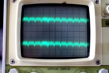
The scope pic you posted before had 3 peaks over 10 divisions with 2ms/division. If I'm not mistaken that equates to 150Hz ripple. not the 100 that would be expected. This seems to imply that you are seeing 3 lots of 50Hz ripple from each of the three bridges?? I'll have to have a think about how that would happen It doesn't seem to fit with what I would expect to be possible....
Below is the measurement of the output of my chipamp (the PS posted in post 2, and later when John Ferrier asked about the "extra" diodes.
Scope was set at 5mv/div and 10mS/div. As you can see it clearly has 100Hz ripple as well as quite a bit of other "noise". measurement was taken with nothing connected to the amp, and inputs open.
As this is the absolute quietest amp I've ever had, I don't know whether the ripple on the output here is considered acceptable or not, or whether the only acceptable ripple is NONE
As I said before I have caps and diodes to rebuild the PS in my integrated amp, I'm in a similar position to you, in that I really need a separate bridge per channel to have a safe margin with current handling (with the diodes I have). Based on what I thought was successful with my chipamp supply (using a bridge and caps per channel off ONE torroidal) I was planning to do the same with the integrated amp. I could use dual transformers (as I have a spare) but they would need to be outside the main case as there is only room for one inside the chassis, and the two transformers are from different manufacturers so I wasn't sure about using them for separate channels...
Tony.
I also found that I can see the hum on the outputs. Using test equipment at 1:00AM after a glass of wine probably isn't the best idea
Now I know you have pretty much decided to rebuild from scratch, but in the interests of knowing what is going on (and also as an excuse to ask about the levels of hum on my outputs) I thought I'd post an observation
The scope pic you posted before had 3 peaks over 10 divisions with 2ms/division. If I'm not mistaken that equates to 150Hz ripple. not the 100 that would be expected. This seems to imply that you are seeing 3 lots of 50Hz ripple from each of the three bridges?? I'll have to have a think about how that would happen It doesn't seem to fit with what I would expect to be possible....
Below is the measurement of the output of my chipamp (the PS posted in post 2, and later when John Ferrier asked about the "extra" diodes.
Scope was set at 5mv/div and 10mS/div. As you can see it clearly has 100Hz ripple as well as quite a bit of other "noise". measurement was taken with nothing connected to the amp, and inputs open.
As this is the absolute quietest amp I've ever had, I don't know whether the ripple on the output here is considered acceptable or not, or whether the only acceptable ripple is NONE
As I said before I have caps and diodes to rebuild the PS in my integrated amp, I'm in a similar position to you, in that I really need a separate bridge per channel to have a safe margin with current handling (with the diodes I have). Based on what I thought was successful with my chipamp supply (using a bridge and caps per channel off ONE torroidal) I was planning to do the same with the integrated amp. I could use dual transformers (as I have a spare) but they would need to be outside the main case as there is only room for one inside the chassis, and the two transformers are from different manufacturers so I wasn't sure about using them for separate channels...
Tony.
Attachments
Last edited:
Well I think I've answered my own question. I took measurements on my old playmaster integrated amp, the one that has always had a hum problem. I hadn't done any measurements or checked for hum without sources connected since I'd put in a bypass switch for the preamp section, basically I added an input on the back so it can be used as just a power amp. Reason I hadn't checked is because my HT-PC is connected on this input and it is noisy anyway (earth loop problem with arial for tuner card as it is a shared connection with many units, basically I need some sort of isolator for it).
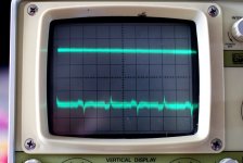
The right channel is the channel with the torroid under it. it has always been the noisier one of the two, noise levels probably double that of the left.
I put the scope on both channels in preamp-bypass mode with 8 ohm dummy loads attached. The right channel shows hum. the left channel a flat line... thinking that maybe my connection on the left channel was dodgy I switched to preamp input and could see noise on both channels, though the left was much lower. I then connected up a source to the preamp bypass, and it was in fact working. I hooked up a speaker to the left channel and even with my ear against woofers or tweeter I could not reliably differentiate if there was any noise there, perhaps late at night with less ambient noise I might be able to hear something.
So I guess the answer to my previous question about whether the only acceptable level of hum on the amps output was NONE, was indeed YES. The only question that remains for me (on the playmaster) is how to get there.
The chipamp is a different matter and the residual hum may be the PS or may be radiated noise, the case is so compact that the toroid is almost touching the chips. Since it was originally designed as a speaker testing amp I'm not overly concerned at this point but I'm sure ultimately my curiosity will get the better of me and I'll do some debugging on it too.
Picture attached. This time with 5mv/div and 5ms/div I think I'm getting the hang of this scope, I couldn't get a stable reading at 5ms/div before.
Tony.
Attachments
Oh, I see I did a typo, I ment secondary winding not primary!
Good thing you brought it up anyway, It made me aware that I must consider phase when joining the two secondary windings for the single-rectifier set up!
Good thing the chip-amp is working again, lets just hope it was some conductive debris somewhere and nothing more serious that can re-occur!
My scope is a fairly old and well used job..sat many years in my dad's garage after he salvaged it from the skip at work.
One of the two test probes have a bad contact and one of the switches can act up, but now that I know this, it's not a problem.
My scope has a calibration output that gives out a 5v P-P signal, so whenever I'm in doubt about the scope, I just hook the probe up to this. Very usefull!
Yes, I did actually notice the strange frequency i\od the ripple I measured.. unless it's was some sort of harmonic, I can't really find a valid explanation.
I doubt that this was tree sets of ripple added together from the three rectifier pairs, that would imply some sort of phase delay and I can't understand how that could happen. Most likely, I made a mistake regarding the time-div setting..
5mV ripple on the output should be audible, but if you have your transformer as close to the chip-amp circuitry as you describe, that may well be an explanation? If it is possible for you to move the transformer, it should be easy to confirm this. I guess that even with grounding and PSU done right it is possible to get induced hum if the field is strong enough. Perhaps some mu-metal will do the job?
Considering the issues I've had, using one rectifier and one set of capacitors per amp channel of one transformer doesn't sound as a good idea..
However, if you are carefull about the connection points, it might work. What I found was that even though the 3 0V connection points I had were not that far apart, it was still enough for local charging pulse currents to create AC/ ripple potential differences. If you decide to try this, it is probably a good idea to do a kitchen table "proof of concept" test-setup before building it in to the amplifier. (as iopposed to what I did..)
If you have two transformers and the voltage and current rating is the same, it should in theory be OK to use these even though they are of different manufacture.
having said that, even if they give the same voltage at no-load, the voltage under load may differ, even if the curren rating is supposed to be the same.
I'd check that out just to make sure that the supply of one channel dosen't "sag" differently than the other.
Will be interresting to see what the issue is with the playmaster amp.. considering the hum is only on the right channel and that channel is closer to the Toroid, it sounds like induced hum.
Not knowing the physical layout, is it possible to move the toroid to see if that has any influence?
Could be that you need to do some magnetic shielding?
Even though it seems that radiation from the toroid was not the root cause of my issues, my expreiments demonstrated that shielding did have an effect.
Guys is your ripple at mains frequency or is it oscillations from the amps?100Hz ripple
Look very carefully at the PSU schematic.
Use a series pair of smoothing caps, use a single bridge rectifier. Temporarily remove the CT to Zero Volts wire connection. You can analyse a dual rectifier using the same method.
Take a pencil and draw along the route that the +ve half cycle current will follow all the way from the secondary end back to the secondary. This is a capacitor charging current so it is allowed to pass "through" the capacitor.
Mark this route in RED.
Take the same pencil and and draw along the route that the -ve half cycle will follow. Mark this route in Blue.
Now add in the CT to Zero Volts wire connection.
Assume just one capacitor needs charging. Colour in the current route for this one capacitor using first the +ve half cycle and then the -ve half cycle.
Can you see the figure of 8 for the charging current?
These coloured in current routes are the charging circuit.
You can do the same coloured current routes for the RCA signal input to amplifier and include the NFB and the input filters.
The signal current circuit (route) MUST NEVER share a piece or part route with the charging circuit.
When you look at the speaker current route you will find that a tiny bit of the route must be shared between the Charging circuit and the Speaker circuit. This tiny path must be VERY SHORT and must be VERY LOW resistance.
You will also find that the NFB part of the signal circuit shares a tiny part of the speaker circuit. This is the tiny bit of PCB trace that Self talks about. This sharing cannot be avoided, so again short and low resistance is important. Fortunately this piece of shared PCB trace is inside the NFB loop and I think this swamps out a speaker to signal effect.
You can now do a current circuit for the power ground including the decoupling caps.
You can also do a current circuit for any ancillaries (relays, soft starts, DC detects etc).
Again the current routes should never share a wire or trace carrying current for both circuits.
By keeping the current routes separate you avoid the voltage drop in one circuit affecting the voltage in another circuit.
Most of these circuits need to reference themselves to other circuits. Do this by allowing the separate circuits to "touch" (not share) each other at a point. This point is the Main Audio Ground.
Last edited:
You Had hum before you put the Xover in. Try and hook up all three amps off one output of the power supply. You need to redo your power supply with proper grounding. Get rid of the steel bolt holding the Xformer too try brass. Andy
No luck finding any brass bolts, closest I came was a store that had threaded brass rods, but they were expensive!
Found some brass bolts on ebay, but they were allso very expensive.
But then I found 10x nylon bolts on e-bay for a fraction of the cost!
Should be about as non magnetic as it gets, and since they were not too expensive, I figured it was worth it as a precaution.
- Status
- This old topic is closed. If you want to reopen this topic, contact a moderator using the "Report Post" button.
- Home
- Amplifiers
- Power Supplies
- A Grounding challenge , please help..