Hi E,
is your PSU like post77?
There he has a dual secondary driving a dual rectifier feeding a pair of smoothing caps with a floating Zero Volts connection.
He than adds on two more PSUs in parallel and each of these have a floating Zero Volts connection.
Each channel fed from ONE Zero Volts connection must remain completely insulated from any other channel inside your casing. But that introduces a severe risk of electrocution.
You must connect all conductive exposed parts to chassis = many grounding loops.
Hi Andrew that IS his power supply, I just added the couloured dots to Elberts schematic. He many posts back tied the three floating 0V's together (but that schematic is as it was when he started the thread). I'm assuming that he does have a safety ground connection, but that is an assumption. Perhaps in post 77 I should have added one connection to the bolt that I suggested, ie a connection to saftey earth.... It was implied but not explicitly stated.
edit: This is what I said in the first post I made:
edit: This is what I said in the first post I made:
Tony.Personally I think I single bridge per channel with the Zero Volts coming from the transformer windings would be safest. That is how I did the powersupply for my Gainclone which has a single traffo, and separate rectifiction and cap bank for each channel. I don't know whether it will be safe to connect zero volts points together with your setup, as you might run into problems with differences in the diodes, not all conducting/rectifiying equally. (note that is just a suspicion, not based on any practical or theoretical knowledge, someone else would be better to answer with respect to your actual implementation I'm just relating what worked for me).
Last edited:
The fundamental mistake is to run 6(!) bridges to 3 pairs of caps from two secondaries. That is why there are ground current problems. Better to wire the two secondaries as one CT, then use one bridge to feed one pair of caps (you can always parallel the caps).
Anything less than this change is merely fiddling. If you don't believe me, try simulating it with every cap different value, every diode different forward drop, and every ground path a 0.1ohm resistor. You will find hum everywhere, yet if done properly all you get is a little supply ripple. I can say no more, if the OP will not fix the basic problem.
Anything less than this change is merely fiddling. If you don't believe me, try simulating it with every cap different value, every diode different forward drop, and every ground path a 0.1ohm resistor. You will find hum everywhere, yet if done properly all you get is a little supply ripple. I can say no more, if the OP will not fix the basic problem.
DF96,
I have no electronics simulations software, but I get your point.
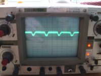
Just to see how this actually applied to my case, I connected the ground wire of my scope to a wire soldered to the 0V trace on the capacitor bank PCB (or area), and I then touched the positive probe on the three different connection points for amplifier 0v (one for each card)
I could measure some noise, relatively simmilar waveform for all measurements but amplitude varying from 0,8-1,5mV
I allso measured between the 0V points them selves and that yielded results along the same lines..
To verify the measurements, I attached ths scope grounding clip and probe to the same point at one of the 0V terminals. That gave a flat line on the scope.
So, 0V potential is not even across the capacitor bank and the connection points, this is now proven and quantified I think.
So from there on, is the magnitude of these measurements significant?
Is it an explanation for the issues I have, or is it an insignificant detail? I have no past experience to judge this by, so please chime in.
I don't mean to be going on here, just wish to make sure I understand what is actually going on in my design. As it is a bit o9f a pain to modify/ rebuild the PSU, I need to be sure that the theory matches the reality.
I have no electronics simulations software, but I get your point.
Just to see how this actually applied to my case, I connected the ground wire of my scope to a wire soldered to the 0V trace on the capacitor bank PCB (or area), and I then touched the positive probe on the three different connection points for amplifier 0v (one for each card)
I could measure some noise, relatively simmilar waveform for all measurements but amplitude varying from 0,8-1,5mV
I allso measured between the 0V points them selves and that yielded results along the same lines..
To verify the measurements, I attached ths scope grounding clip and probe to the same point at one of the 0V terminals. That gave a flat line on the scope.
So, 0V potential is not even across the capacitor bank and the connection points, this is now proven and quantified I think.
So from there on, is the magnitude of these measurements significant?
Is it an explanation for the issues I have, or is it an insignificant detail? I have no past experience to judge this by, so please chime in.
I don't mean to be going on here, just wish to make sure I understand what is actually going on in my design. As it is a bit o9f a pain to modify/ rebuild the PSU, I need to be sure that the theory matches the reality.
Attachments
You Had hum before you put the Xover in. Try and hook up all three amps off one output of the power supply. You need to redo your power supply with proper grounding. Get rid of the steel bolt holding the Xformer too try brass. Andy
I've been thinking about that bolt holding the transformer in place.. I assume you are thinking what I'm thinking, that it could focus or direct flux-lines towards the x-over board?
If I can get hold of a suitable brass-bolt (hardware stores ain't what they used to be..), I'll replace it!
As for connecting all amps to one PSU output, I'm not sure I'll be able to do it, but I'll give it a try!
The fundamental mistake is to run 6(!) bridges to 3 pairs of caps from two secondaries. That is why there are ground current problems. Better to wire the two secondaries as one CT, then use one bridge to feed one pair of caps (you can always parallel the caps).
Anything less than this change is merely fiddling. If you don't believe me, try simulating it with every cap different value, every diode different forward drop, and every ground path a 0.1ohm resistor. You will find hum everywhere, yet if done properly all you get is a little supply ripple. I can say no more, if the OP will not fix the basic problem.
DF96,
I've started to think about practical solutions for modifying my PSU to a "conventional" design with proper connection and ground points that will elliminate charging pulses etc as a possible problem.
The obvious solution is to connect the two secondaries with a center-tap and use one rectifier.
It should however allso be OK to have each secondary feed a rectifier and then connect 0V downstream of the rectifier. as this solution is described in Bob Cordells amplifier book, I guess it should work.
I have two practical issues. The rectifiers I have used is rated a bit too low.
Allso, I donæt have much room for installing a higher capacity rectifier which is inevitably physically larger.
Going with a conventional single or dual rectifier PSU design, is there anything that should discourage me from using 2 or 3 rectifier bridges in parallel? this would of course mean connecting them together with the capacitor bank at ONE point, not several as I understand that this wouild cause charging currents flying all over the place.
Elbert; Testing your O volt points with a scope is no good, the ground lead on the scope is GROUND and will mess up your meserments unless you isolate your scope.
Tie all three amps off the same supply just for testing. The steel bolt should be an electromagnet, NG. You should also test with the transformer out of the box.Andy
Tie all three amps off the same supply just for testing. The steel bolt should be an electromagnet, NG. You should also test with the transformer out of the box.Andy
Yes this is the way to go and get bigger rectifiers.The obvious solution is to connect the two secondaries with a center-tap and use one rectifier.
Andy
Elbert; Testing your O volt points with a scope is no good, the ground lead on the scope is GROUND and will mess up your meserments unless you isolate your scope.
Tie all three amps off the same supply just for testing. The steel bolt should be an electromagnet, NG. You should also test with the transformer out of the box.Andy
Perhaps I was not too clear in my explanation of the measurement.. I simply used the scope to measure voltage potentials between different spots in the 0V architecture, not relative to any other ground. The fact that I didn't measure anything when measuring on the same spot as opposed to two different spots should verify that the measurements are OK.
Yes, I can se that bolt acting as an electro-magnet, a good way to put it!
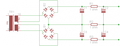
So, I've done a schematic on a possible new power supply..
Here I've only used one pair of rectifier bridges, but for current rating I would like to use perhaps one bridge each in parallel to B1 and B2, yet wired exactly the same way.
I have not placed the supply terminals at the same point as the connection points of the bridge rectifiers.
Rather, the rectifiers are connected to one "bank" of capacitors, and that bank is then connected to another capacitor bank through 1 ohm resisitors. from that second bank, the suplly to all thre amplifiers are then taken.
This solution is possible for me to physically realize and to the best of my understanding, it should be according to "accepted and proven" principles, as described both here and in Bob Cordells book.
Should I go for this???
Attachments
I am puzzled why you are using two bridges when one will do the job? Connecting bridges in parallel will not achieve anything unless you include balancing resistors.
Regarding your tests, you have now seen how two places connected by a thick piece of wire can still be at different potentials. This is the essential insight needed when designing grounding schemes. Any other grounding route joining those two places together will carry current, because of Ohm's law. It may be mA, instead of the amps of the direct route, but still enough to inject hum.
Note that the 1 ohm resistor in your cap ground connection could, with advantage, be replaced by a piece of wire, but it will help if you still think of it as a resistor.
DF96,
Two reasons I have 2 rectifiers in the schematic;
1:
The rectifiers I have are only rated for 10-15 amps, so just one is pushing it considering I have a 600 VA toroid and 120000uF worth of reservoir caps.
2:
I read this in Bob Cordells book:
"An alternative arrangement employs two secondary windings and two bridge rectifiers (as shown in figure-same as my schematic). One possible advantage to this design is that it avoids the circulation of direct current through the transformer windings when the positive and negative rail load currents are different. The flow of direct current through the transformer windings should be avoided, as it can degrade transformer performance and sometimes create transformer buzzing.
Toroid transformers are more sensitive to this effect than transformers of conventi0nal construction.
The rectifier current pulses for each half of the supply do not circulate through ground, but rather circulate locally. This may improve management of rectifier noise. Indeed there is no direct connection of the secondary windings to ground."
So, if I can gert sufficient rectifier current rating (using components i have), and get the possible benefits, there seems to be no drawbacks, I figured why not?
Regarding the 1 ohm resistors, this is to acheive a so called "split reservoir capacitor" solution, allso described in Bob's book. It says that it can have a " remarkable effect on reducing ripple and noise content.
If remarkable effects can be had for the price of two resistors, I'll take it
Yes seeing is believing..
One thing is understanding principles and theoretical models, but my experience is that something which is theoretically logical is not allways relevant. the effect might be there but it might at the same time be insignificant or owershadoweed by other issues.
The scope measurement sure gave me a valuable insight, one is not used to the concept of local current and voltage differences inside a "local" conductor envelope like this!
PS!
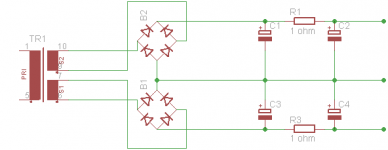
I made one mistake in the previous schematic, the resistor between the first and second capacitor bank 0V was not supposed to be there! Sorry!
Two reasons I have 2 rectifiers in the schematic;
1:
The rectifiers I have are only rated for 10-15 amps, so just one is pushing it considering I have a 600 VA toroid and 120000uF worth of reservoir caps.
2:
I read this in Bob Cordells book:
"An alternative arrangement employs two secondary windings and two bridge rectifiers (as shown in figure-same as my schematic). One possible advantage to this design is that it avoids the circulation of direct current through the transformer windings when the positive and negative rail load currents are different. The flow of direct current through the transformer windings should be avoided, as it can degrade transformer performance and sometimes create transformer buzzing.
Toroid transformers are more sensitive to this effect than transformers of conventi0nal construction.
The rectifier current pulses for each half of the supply do not circulate through ground, but rather circulate locally. This may improve management of rectifier noise. Indeed there is no direct connection of the secondary windings to ground."
So, if I can gert sufficient rectifier current rating (using components i have), and get the possible benefits, there seems to be no drawbacks, I figured why not?
Regarding the 1 ohm resistors, this is to acheive a so called "split reservoir capacitor" solution, allso described in Bob's book. It says that it can have a " remarkable effect on reducing ripple and noise content.
If remarkable effects can be had for the price of two resistors, I'll take it
Yes seeing is believing..
One thing is understanding principles and theoretical models, but my experience is that something which is theoretically logical is not allways relevant. the effect might be there but it might at the same time be insignificant or owershadoweed by other issues.
The scope measurement sure gave me a valuable insight, one is not used to the concept of local current and voltage differences inside a "local" conductor envelope like this!
PS!
I made one mistake in the previous schematic, the resistor between the first and second capacitor bank 0V was not supposed to be there! Sorry!
Attachments
Last edited:
In most power amps the current drawn from the two supply rails is necessarily nearly equal, so I would not worry about DC in the transformer. If it was as serious as Cordell implies then half-wave rectification would not be possible. Using two bridges as you have will at least have the advantage of halving heat per bridge, as each diode can rest while its opposite number is conducting.
Maybe you need bigger rectifiers, or smaller caps. Adding balancing resistors to paralleled bridges may sufficiently reduce peak current that you could get away with one bridge. Huge caps create problems, although some people seem to be impressed by them. What cap value do you actually need? I assume you have calculated allowable voltage drop and/or ripple?
Maybe you need bigger rectifiers, or smaller caps. Adding balancing resistors to paralleled bridges may sufficiently reduce peak current that you could get away with one bridge. Huge caps create problems, although some people seem to be impressed by them. What cap value do you actually need? I assume you have calculated allowable voltage drop and/or ripple?
Well, Cordell doesn't imply that it is a serious issue, more like a potential benefit.
If that benefit is real or not, well, as long as there is no drawback to this and it allows me to use two rectifiers in stead of one, I'm happy!
I don't really have room for larger rectifiers, so If I can use the ones I've got, that would obviously be a big advantage for me.
Having said that, I feel that using two rectifiers leaves me with little margin.
Provided I keep to the schematic in terms of connection points, do you see any problems with using 2 or 3 rectifiers in parallel??
I haven't really done any calculations on the reservoir cap sizes, I just followed the guidelines in the magazine article describing the Crescendo ME amplifier project.
As with most things, I guess there is a point of diminishing returns for reservoir cap size as well, but I don't think I've gone over board with 40000 uF per amplifier channel, that seems to be pretty much in the ballpark compared to other designs and projects out there..
Use one bigger bridge per amp as shown in post #93. And all your troubles will be gone.
Problem is that would requirte a rectifier that is physically bigger than the multiple smaller ones I have now and there is not much room for that in my chassis!
remove all 5 extra bridge rectifiers.
remove two of the three banks of smoothing caps.
wire up the only remaining bridge rectifier and then test through the bulb tester.
Wire up one bank of smoothing caps and test through the bulb tester.
connect one power amp and test through the bulb tester.
Short the power amp input. Measure the output noise of that one channel in mVac using you Digital VoltMeter (DVM).
Now connect up the second channel power amp to the same PSU, test through the bulb tester.
Now measure the shorted input power amplifiers output noise. Are they both low? has the first one got worse?
report back.
Andrew,
You describe the only logical process here..
My problem is that modifying the PSU as you describe here will in reality involve a teardown and (partial) rebuild pretty much as required for doing the full PSU modification anyway.
even with a bulb tester, I'm nor comfortable hooking up the power connections without proper termination points in place, the wires are simply to short and stiff and space to constrained. even with a bulb tester, the accumulated charge in the capacitors can easily fry stuff if a wire slips and touches the wrong place. Been there before you know!
But once the power supply is modified, I will of course progres to test as per your description annyway!
Of course, re-doing the PSU without testing first might seem like a stupid thing to do, but this time arround, It will be a "conventional" PSU, adhering to established principles of layout and connections. if that doesn't work, then nothing will work, and if it dosen't solve my problem, then the problem is really elsewhere.
- Status
- This old topic is closed. If you want to reopen this topic, contact a moderator using the "Report Post" button.
- Home
- Amplifiers
- Power Supplies
- A Grounding challenge , please help..