Stupid question ?
What do diodes 2, 3, 5, & 6 do ? (The four shorted A to K.) I've seen this before with bridge circuits. What am I missing ? ? ??
.
Not a stupid question at all
") The BYV32E's are a dual diode in a 3 pin TO220 package. the cathodes share a common pin but the annodes have separate pins. I used three for each bridge and the extra diodes in the packages where I was only using one of the diodes I shorted to reduce the possibility that they could pick up noise if I left one end floating I grabbed the image from my blog page and without the text that went along with it it doesn't make a whole lot of sense!
The BYV32E's are a dual diode in a 3 pin TO220 package. the cathodes share a common pin but the annodes have separate pins. I used three for each bridge and the extra diodes in the packages where I was only using one of the diodes I shorted to reduce the possibility that they could pick up noise if I left one end floating I grabbed the image from my blog page and without the text that went along with it it doesn't make a whole lot of sense!The PS I'm working on at the moment I'm going to use 4 X BYV32E's and wire the two diodes in parallel in each package... I wasn't sure if this was a good idea when I did the one you have shown the image for, but I'm getting more adventurous
Reason I showed them on the schematic was because I was using expresspcb to do the layout for my verroboard, and having the actual components accurately represented allowed me to use the netlist to check the board layout against the circuit... probably overkill for such a simple circuit but nice to check
Tony.
Last edited:
Elbert, have to be quick, my lunch hour is over. I used lead simply because I could easily shape it (and solder it), and it was available in sheets at the local hardware shop. I figured that since it was dense it should block EMI well. I didn't try any other materials.
I thought about mentioning putting a piece of steel (it looks like your bulkhead is aluminium?) in between but JCX beat me to it
Tony.
I thought about mentioning putting a piece of steel (it looks like your bulkhead is aluminium?) in between but JCX beat me to it
Tony.
Makes sense to use lead from a practical point of view then in terms of cutting and shaping.
Lead is not a particularily good conductor, (as far as metalls go), so a better conducting material should in theory have been more optimum for shielding electric field.
Allso, lead has a verty low magnetic permeability, i,e, magnetic flux lines will not seek to flow through it, thus it is not a suitable magnetic shield either.
Perhaps there are some other properties that makes lead suitable?
Or perhaps it was just good enough for your applications?
Annyway, off to get some mild steel sheet here!
Sorry if this has already been covered, but you do realise that if you connect two rectifier bridges to one secondary you have effectively lost all control of PSU grounding? This may not show up in a simulation, as that will assume that all diodes and all capacitors are identical. You can just about get away with this provided the two DC supplies are used for isolated circuits with no other connections between them (except via transformers or opto-isolators). You can ground either of the two PSU 'grounds', but the other one will then become dirty - you can't ground both of them.
Lead is not a particularily good conductor, (as far as metalls go), so a better conducting material should in theory have been more optimum for shielding electric field.
Yes but the troublesome fields from transformers are nearly always the magnetic ones, not the electric.
Allso, lead has a verty low magnetic permeability, i,e, magnetic flux lines will not seek to flow through it, thus it is not a suitable magnetic shield either.
That is true for a DC magnetic field - like might come from a permanent magnet. However here with an AC field there's another way to shield - by eddy current effects. That's the reason lead is working to a degree - but steel would be far better because of its higher permeability, meaning the skin depth is shallower. Oh and steel is more conductive than lead, so better still.
Annyway, off to get some mild steel sheet here!
Excellent
Sorry if this has already been covered, but you do realise that if you connect two rectifier bridges to one secondary you have effectively lost all control of PSU grounding? This may not show up in a simulation, as that will assume that all diodes and all capacitors are identical. You can just about get away with this provided the two DC supplies are used for isolated circuits with no other connections between them (except via transformers or opto-isolators). You can ground either of the two PSU 'grounds', but the other one will then become dirty - you can't ground both of them.
Yes, this actually occured to me at one point. That is why I connected the PSU grounds together at the reservoir capacitors!
So, steel plate shielding it is..
Looks like it is going to be very tricky for me to enclose the Toroid, so I'll go for placing steel sheet between the toroid and the x-over card..
But what would be the better strategy?
One thick plate of steel or several thinner sheets stacked? Or is it only a matter of thickness irrespective of sheets/ layers?
Last edited:
Hi Elbert I did a bit of a google search on lead as a shield and yes your points are very valid, I probably would have been better off with a steel cylinder roughly the size of the traffo possibly even a tin can(if big enough) would work! I did it probably at least 10 years ago (possibly even 15 years ago) the amp is 24 years old and googling wasn't a natural action back then I knew nothing about EMF/EMI and just figured that lead being dense should block it well (I'd determined it was radiation by moving the transformer outside the chasis which reduced the noise to almost nothing).
The lead definitely makes quite a difference, though I never did any tests with a mic to quantify the absolute difference in noise levels. Perhaps the sheer density of the lead works to block rather than dissipate the EMF... I don't really know, though after what I read today mild steel is probably a better choice!
Tony.
I knew nothing about EMF/EMI and just figured that lead being dense should block it well (I'd determined it was radiation by moving the transformer outside the chasis which reduced the noise to almost nothing). The lead definitely makes quite a difference, though I never did any tests with a mic to quantify the absolute difference in noise levels. Perhaps the sheer density of the lead works to block rather than dissipate the EMF... I don't really know, though after what I read today mild steel is probably a better choice!
Tony.
Yes, sometimes we just have to fix something, and sometimes it just works!
As you say, from available information, there seems to be better candidates than lead when considering the electrical and magnetic properties.
The shielding properties of lead is of course most relevant with respect to radioactive radiation like high-energy electrons (Beta-radiation) and gamma and x-rays, mainly due to the high density of lead, but I've found no information that the properties making lead effective for these high energy forms of radiation could have any effect on low frequency and low density electro-magnetic radiation.
That would be cool though, but I guess we are talking about two very different domains of physics!
OK, that wasn't clear from the diagrams. This issues catches some people out, especially as simulations don't show it.Yes, this actually occured to me at one point. That is why I connected the PSU grounds together at the reservoir capacitors!
Lead will be fine, but unnecessarily heavy, for electrostatic shielding but useless for magnetic shielding as it is not ferromagnetic and is a poor conductor. You need mu-metal for that.
My mistake, the diagram I posted showed the PSU layout as it was BEFORE I modified it and connected the ground points together!
But thanks for taking an interrest and making the observation nevertheless!
Mu-metall seems to be very effective, but unfortunately, it is rather expensive.
This is why I'll throw in some steel sheet to see if that can get rid of the worst so my last precious strip of mu-metal doesn't get overloaded and saturated!
I would try replacing that bulkhead between the PSU and the rest with a 6mm or 8mm thick steel plate. Insulate as necessary.
The plate should be a close fit at all the edges where it meets the chassis.
Try to find out which part of the amplifier is contributing most to the noise.
You can measure the noise directly at the amplifier outputs. You don't need speakers connected.
Start by shorting all your inputs and measure the noise at all your outputs.
Remove one short and remeasure.
You may find that just one circuit is responsible for most of the noise.
If that fails to detect the noise source then try shorting the outputs from the crossovers. Again start by shorting all of them. and remove one short at a time.
If that does not reveal your source of noise then move to the amplifiers. disconnect all but one from the PSU. measure. Swap to another measure etc.
You may still find it is a grounding problem.
So,
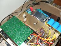
Got one steel plate ready and in place.
It did reduce the hum with about 2 dB, so not so much as the strip of mu-metal which reduced hum by about 3-4 dB even though it was not as large as the steel plate.
As I have the steel available, I'll try adding a second steel plate as well.
At the end of the day, I'm tempted to order another sheet of mu-metal. If I stick that to one of the steel plates covering the complete area, or perhaps both, I should, based on the experimental results so far, get a fairly good result.
As it is now, with both the steel plate and the strip of mu-metal, the hum in the speakers are not much louder than the physical hum emitted from the actual amplifier.
Andrew,
Your suggestion for ferretting out any circuit source of hum seems very good. I've actually done this to some extent ,but not as systematically and methodically as you have described. I will definitively give that a go once I've got the magnetic shielding in place!
Attachments
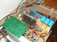
Just got the second steel plate in place, and that yielded about another 1,5-2 dB reduction of hum, so all in all, with two steel plates and a strip of mu-metal the hum in the speakers is reduced by about 8 dB.
This is not too bad, and I guess with some additional mu-metal (just ordered a sheet), it might yet improve a bit.
Now, it seems that this is getting close to how much I can improve things with this approach.
I switched off the pre-amp and that reduced hum by a small tad, not enought so I couild measure it reliably, but it was audible with the ear next to the speaker.
I then disconnected the pre-amp from the amplifier and swithed the pre-amp on and off again. This time there was no additional hum, so it was not the pre-amp transformer.
Either, there is some hum present on in the pre-amp signal, or there is something else "wrong" causing some additional hum with the pre-amp connected...
Perhaps it's the amplifier toroid radiating hum in to the Pre-amp which is then fed back in to the input?
I noticed that if I cranked up the volume controll on the prer-amp, the hum would increase.
Will try to move the pre-amp after dinner..
Moving the pre-amp allso removed the hum from the pre-amp, so apparently this was the amplifier transformer inducing some hum there.
That should allso rule out any sort of signal/ ground issue between amp and pre-amp.
I have not rotated the transformers as there is little room to do so because of the wire routing.. But I'll see if I can manage to do it, should it give a noticeable effect, it is well worth to adjust the wiring layout of possible!
Having said that, the transformer primary and secondary wires exit on the side facing away from the rest of the amp, which I understand is favourable.
That should allso rule out any sort of signal/ ground issue between amp and pre-amp.
I have not rotated the transformers as there is little room to do so because of the wire routing..
But I'll see if I can manage to do it, should it give a noticeable effect, it is well worth to adjust the wiring layout of possible!Having said that, the transformer primary and secondary wires exit on the side facing away from the rest of the amp, which I understand is favourable.
Having said that, the transformer primary and secondary wires exit on the side facing away from the rest of the amp, which I understand is favourable.
Not always entirely predictable. I've learned, the hard way, to leave the wires long until I have optimized orientation.
Sheldon
Andrew,
I shorted the input to all three amplifier cards and the RCA input.
I did this with the loudspeaker still connected.
This lead to no noticeable reduction in hum.
I then removed the shorts, starting with the RCA input, then the amplifier cards.
When I removed the short from the input on the card driving the midrange, there was a very faint increase in noise and hum, but not much. (hardly significant)
I have allso tried to remove the power connection from the x-over card, this made no difference.
Any conclusions that can be drawn from this so far??
Regarding shorting the outputs on the x-over card, this should effectively be the same as shorting the inputs on the amplifier cards, there's only a 10 cm piece of shielded wiere difference.
So, I didn't do this as this is extremely difficult to get at.
I'll try to disconnect two of the amplifier cards from the PSU, then re-connect them back one at a time as you instructed. A bit fiddly due to the thick wires and the termination though..
Learning the hard way seems to be what I do best!
How big was the change you acheived?
Read from here to post 864: http://www.diyaudio.com/forums/soli...age-audio-power-amplifier-85.html#post1875635 The input stage is the part in the lower right corner.
Then check post 892 for a second amp in a different layout. Note the position of the transformer - not what you might predict.
Sheldon
- Status
- This old topic is closed. If you want to reopen this topic, contact a moderator using the "Report Post" button.
- Home
- Amplifiers
- Power Supplies
- A Grounding challenge , please help..