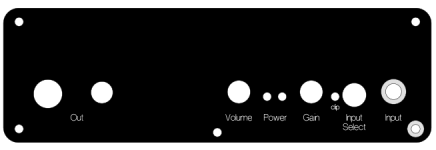
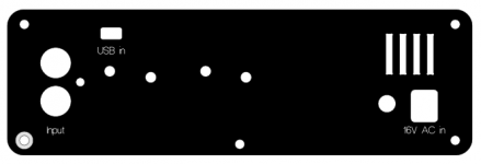
As promiss here are 2 front panels with and without vents, in fpd, soon will release the same ones in dxf.
Thank you!
")
Is the clipping light coming on in either case, or is it all audible? Do you have access to a scope to see the output waveform?
I played around with Rob Robinette's headphone power calculator and definitely agree this doesn't seem to be working as intended.
Data points:
Bass boost on:
50 ohm 110 dB/mW: expected ~0.4Vrms @ 115dBSPL: clipping indicator turns on at half volume on max gain
300 ohm 103 dB/mW: expected ~2.2Vrms @ 115dBSPL: clipping indicator turns on at half volume on 2nd gain notch, audible clipping past that (bass-heavy tracks only)
70 ohm 93 dB/mW: expected ~3.3Vrms @ 115dBSPL: clipping indicator turns on at half volume on max gain for bass-light tracks, clipping indicator turns on at half volume on first gain notch, audible clipping past that
Bass boost off: clipping indicator turns on only at high volume on max gain.
Unfortunately my scope (just a little Rigol) and function generator are currently in storage a couple thousand miles away.
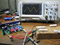
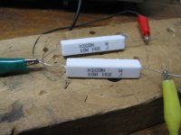
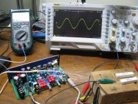
I set up a test this evening with a (nearly) 50 ohm load, photos below. Each channel has 33R in series with 16R = 49 ohms. This is with the attenuation resistors on the board jumpered to get the full output swing.
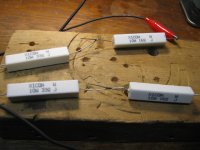
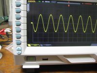
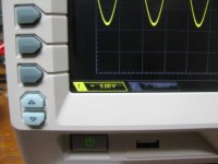
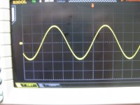
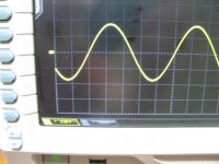
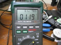
The first photo is the test setup. The next is the load resistors. I'm playing a 1KHz tone through the computer. The scope is set for 5V/division. The next 3 show the level, about 9Vpeak = 6.3Vrms. That isn't the maximum either, that is just as high as max volume on the laptop and max gain and volume on the ODA would give, without me having to break out the signal generator to go higher.
The absolute (clipping) max is probably around 7Vrms. Also note in the photo (although hard to see) the clipping LED isn't on at the 9V peak level yet. But this is enough to show there is no clipping problem into 49R, at least all the way up to 9Vpeak, which is about 4 times more voltage swing than is needed via that loudness calculator spreadsheet. The bass boost at 3dB would roughly double the gain at low frequencies. But only 1.5Vrms is needed for 115dB so there is still plenty of headroom.
Hey if you want to box it up and send it to me I'll take a look! I did the same for Alex.
I have that solder sucker that makes it easy to replace parts if needed. No need to send the power adaptor, I have a bunch here.Also - what is the output level of your source? Since no scope you could just play a 1kHz tone, or whatever frequency is within spec for your DMM on AC, and measure with the DMM. If your source level is too high you may need to add those attenuation resistors since you are using bass boost. With the atten resistors bypassed and no boost you get gains of 1x, 2x, 4x, and 6x. Boost will double that at the low frequencies to 2x, 4x, 8x, and 12x which may be what is causing the clipping. If you put the atten resistors in then with bass boost you will get 1x, 2x, 4x, and 6x at low frequencies with the 1/2x, 1x, 2x and 3x at the higher frequencies. With the attenuation resistors your maximum output swing gets cut in half from 7Vrms to 3.5Vrms or so, but that is still over twice what is needed for your 50R cans.
Attachments
Last edited:
I was using the built-in ODAC, which I believe is 2Vrms.
Thanks for the kind offer! I may take you up on that later
Ah, you have an 808 too! Those absolutely rock.
I just edited the last paragraph about the attenuation resistors with more info. More I think about it, that could be the problem. If you need those two resistors just let me know and I'll drop a couple in the mail.ODA pre-amp wiring, testing, and the NJM4556AM
Since Mouser can't supply the MUSES8820E chip for another couple of months I decided to go ahead and build up the pre-amp section using a NJM4556AM. That is the surface mount version of the NJM4556A chips used in the O2 and the SIP package version used as the ODA outputs.
The nice thing about the NJM4556AM is it can drive cable capacitance. Someone could easily plug a long RCA cable into the pre-amp jacks and exceed the 100pf or so drive capability of a lot of op amps. No troubles there with the NJM4556AM.
I've wired the pre-amp up as a unity gain buffer. R57 and R62 are zero ohm jumper resistors to run the output of the NJM4556AM directly to the pre-amp out. Those resistor pads are in there to add isolation resistors, if needed, with other op amps to help solve the cable capacitance issue. Not needed with the NJM4556AM.
R52 and R56 are 1.5K, while R49 and R55 are left unpopulated, giving the unity gain. Then 180pF compensation capacitors are added for C41 and C43. R90 is another zero ohm jumper resistor to attach the RCA jack ground.
I've run the signal feed lines from JP7, which is the output of the input select switch, to JP20 which is the pre-amp chip input. So the pre-amp stage gets fed from whichever input jack is selected, the rear RCA or the front 3.5mm. The pre-amp stage also shares the 10K ground return resistors for the input stage, R16 and R17. This is important when using the pre-amp chip (as opposed to running signals directly to the pre-amp out jack and not using IC8), since the pre-amp chip's input bias current needs a path to ground.
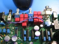
* The first photo shows the pre-amp section of the ODA board before being built up.
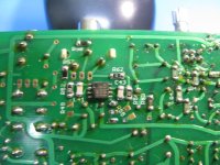
* The next photo shows the NJM4556AM chip and other parts listed above installed. The molded dot on the chip goes toward the board edge. Best to install the chip last to help avoid static damage.
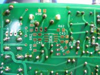
* The next photo shows the signal jumper lines from JP7 to JP20. The middle hole of JP20 is unconnected and not used.
Since Mouser can't supply the MUSES8820E chip for another couple of months I decided to go ahead and build up the pre-amp section using a NJM4556AM. That is the surface mount version of the NJM4556A chips used in the O2 and the SIP package version used as the ODA outputs.
The nice thing about the NJM4556AM is it can drive cable capacitance. Someone could easily plug a long RCA cable into the pre-amp jacks and exceed the 100pf or so drive capability of a lot of op amps. No troubles there with the NJM4556AM.
I've wired the pre-amp up as a unity gain buffer. R57 and R62 are zero ohm jumper resistors to run the output of the NJM4556AM directly to the pre-amp out. Those resistor pads are in there to add isolation resistors, if needed, with other op amps to help solve the cable capacitance issue. Not needed with the NJM4556AM.
R52 and R56 are 1.5K, while R49 and R55 are left unpopulated, giving the unity gain. Then 180pF compensation capacitors are added for C41 and C43. R90 is another zero ohm jumper resistor to attach the RCA jack ground.
I've run the signal feed lines from JP7, which is the output of the input select switch, to JP20 which is the pre-amp chip input. So the pre-amp stage gets fed from whichever input jack is selected, the rear RCA or the front 3.5mm. The pre-amp stage also shares the 10K ground return resistors for the input stage, R16 and R17. This is important when using the pre-amp chip (as opposed to running signals directly to the pre-amp out jack and not using IC8), since the pre-amp chip's input bias current needs a path to ground.
* The first photo shows the pre-amp section of the ODA board before being built up.
* The next photo shows the NJM4556AM chip and other parts listed above installed. The molded dot on the chip goes toward the board edge. Best to install the chip last to help avoid static damage.
* The next photo shows the signal jumper lines from JP7 to JP20. The middle hole of JP20 is unconnected and not used.
Attachments
Last edited:
Sine wave tests at 32R and 16R
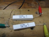
Here are photos of some tests of the ODA running sine waves into a 33R load and a 16R load. These will produce temperatures about 2x - 3x more than actual music.
* The first 2 photos are the test setup and the 33R load resistors.
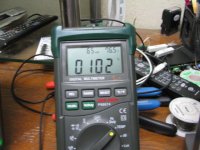
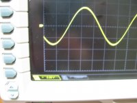
* Next is the steady state temperature of the output chips, 119F, and the waveform. No clipping at 9Vpeak = 6.4Vrms. This is in free air though, in the box it would probably go up another 10 - 15F, so I would still recommend only sine wave testing for 5 minutes at a time then letting things cool down. Again, real music doesn't have this problem because the average level is 2x - 3x less than the peaks. Keep in mind with this test we are delivering 6.4 ^ 2 / 32 = 1.28 watts to the load!
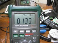
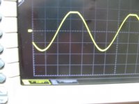
* Next are the 16R load resistors, steady state temp of 133F, and waveform. Here we finally have some clipping at 9Vpeak. The second waveform is the output reduced to 8Vpeak = 5.6Vrms, which is now clipping-free. The power delivered to the load is 2.0 watts.
* The last photo is the rear panel temperature. This is with the 16R load and pure sine waves, pretty much the worst case situation. And the panel is not attached to the metal box which will heatsink even more. 102F, which isn't bad at all.
Here are photos of some tests of the ODA running sine waves into a 33R load and a 16R load. These will produce temperatures about 2x - 3x more than actual music.
* The first 2 photos are the test setup and the 33R load resistors.
* Next is the steady state temperature of the output chips, 119F, and the waveform. No clipping at 9Vpeak = 6.4Vrms. This is in free air though, in the box it would probably go up another 10 - 15F, so I would still recommend only sine wave testing for 5 minutes at a time then letting things cool down. Again, real music doesn't have this problem because the average level is 2x - 3x less than the peaks. Keep in mind with this test we are delivering 6.4 ^ 2 / 32 = 1.28 watts to the load!
* Next are the 16R load resistors, steady state temp of 133F, and waveform. Here we finally have some clipping at 9Vpeak. The second waveform is the output reduced to 8Vpeak = 5.6Vrms, which is now clipping-free. The power delivered to the load is 2.0 watts.
* The last photo is the rear panel temperature. This is with the 16R load and pure sine waves, pretty much the worst case situation. And the panel is not attached to the metal box which will heatsink even more. 102F, which isn't bad at all.
Attachments
-
 IMG_2827.JPG167 KB · Views: 30
 -
 IMG_2825.JPG163.3 KB · Views: 43
 -
 IMG_2824.JPG115.9 KB · Views: 33
 -
 IMG_2823.JPG117.3 KB · Views: 36
 -
 IMG_2821.JPG137.7 KB · Views: 37
 -
 IMG_2820.JPG127.7 KB · Views: 37
 -
 IMG_2819.JPG161.9 KB · Views: 40
 -
 IMG_2818.JPG147.7 KB · Views: 42
 -
 IMG_2817.JPG220.9 KB · Views: 61
Last edited:
Clipping
FYI,
I am using my AKG Q701's now and they are :
Impedance @ 1kHz: 62 ohms; Sensitivity: 105 dB SPL/V
The player I use is JRiver Media Center R18.
I notice this am that using these headphones and listening to certain cuts I see clipping a lot at gain position 3 and 4 and low volume levels.
I never use these gains for normal listening, its just not needed for me at all. But I cranked up the gain just for grins and saw the clipping light come on more than I have ever seen it...
Turns out that the particular track I was listening to is recorded very "hot" and is more prone to clipping etc....
U use replay gain in the player and volume leveling to make all the songs be at the same volume level etc....I looked at the replay gain on these tracks and they are -16db etc!
If I use the volume leveling feature in JRiver the attenuation is applied and the clipping stops.
Again this is only on the higher gain settings which for me I never use....I always use the lowest gain setting etc.
I don't use the volume leveling replay gain feature when I listen seriously I am always tinkering with the volume. LOL.
I also noticed that if I slightly reduce the software volume setting in JRiver from 100% to 99% or lower in most cases the clipping in these higher gain selections is also minimized.
So many switches and interactions.....aint this fun!!!
The ODA here is perfroming flawlessly!!
Great Job AGDR!
Alex
Alex - that is really good point to keep in mind.
The ODA, like NwAvGuy's O2 headamp, has the volume control *after* the gain stage. So if the gain stage has clipping, no amount of adjusting the volume control is going to help. That is just the opposite of amps that have the volume control in front of everything. With those amps lowering the volume will reduce clipping. But with the O2, or ODA, the only thing that will reduce clipping is the gain switch or lowering the level of the source input at the source.
Given this, you can see why I included the clipping indicator! I was an advocate of that on the O2 pretty much from the day NwAvGuy released it. People are getting clipping with their O2's under some conditions and don't realize it. I had mentioned the issue to NwAvGuy a couple of times but he didn't think it was that important. I disagree.
The ODA's attenuation resistors are also on the output of the gain stage, essentially after the gain stage, so they won't help with the clipping issue either. The purpose of the attenuation resistors is to allow more travel on the volume pot. What i posted for dace above (adding the attenuation resistors) may not help with a "hot" source. The solution there is to go back to what I posted in the O2 mods thread for attenuation. The 274R input resistors can be increased, say to 5K, to form a voltage divider with the input 10K ground return resistor, at the expense of adding some Johnson noise from that higher valued resistor.
Last edited:
Alex - I keep getting caught by the 30 minute edit timeout. One more thing too add here. With either the O2 headamp or the ODA it is best to use the lowest gain switch setting that gives adequate volume since the volume control is in the middle, to avoid clipping.
For example, gain swith setting #2 and the volume pot most of the way up is not the same as gain switch setting #3 and the volume pot most of the way down. They may sound the same in terms of level, but the second way with the gain switch at the #3 setting may clip where the first way with the gain switch at the #2 setting may not.
I really should add this to the "operating" part of the build instrucitons. It is something unique to the O2 and ODA.
One more thing too add here. With either the O2 headamp or the ODA it is best to use the lowest gain switch setting that gives adequate volume since the volume control is in the middle, to avoid clipping.For example, gain swith setting #2 and the volume pot most of the way up is not the same as gain switch setting #3 and the volume pot most of the way down. They may sound the same in terms of level, but the second way with the gain switch at the #3 setting may clip where the first way with the gain switch at the #2 setting may not.
I really should add this to the "operating" part of the build instrucitons. It is something unique to the O2 and ODA.
Agree absolutely!!
I almost always use the lowest position listening.....with my headphones all of them will play extremely loud to the point of hearing impairment....not good!!
With most dacs etc that I have used the output is 2.0 or 2.25 volts, ie the ODAC and the HRT MSii+. No need for more gain here!
With a portable amp, and the O2 really isn't that portable you might be using a source that needs a gain boost...
I clipped the resistors in my O2's to have unity gain in one of the settings.
Alex
Last edited:
With most dacs etc that I have used the output is 2.0 or 2.25 volts, ie the ODAC and the HRT MSii+. No need for more gain here!
Exactly! That is why the attenuation resistors in the ODA. With an amp ouputing 2 volts and headphones only needing 1.5 volts or less, but need more current, not only is gain not needed the 1x is too much. The attenuation resistors cut that to 1/2x to give more travel on the volume pot. What you are left with in that gain position is the current buffer with 1/2x voltage gain. That is what all my sources, except the laptop, work best with.
With a portable amp, and the O2 really isn't that portable you might be using a source that needs a gain boost...
I completely agree. Interesting bit of history there. When NwAvGuy / RocketScientist first showed up inthe spring of 2011 I was posting quite a bit on AMB's website forum. I missed all his initial posts - and banning - at Head-Fi, but then he pops up on AMB's forum and proceeds to insult AMB over the mini^3, and especially the virtual ground. I'm not using the word "insult" lightly either. Statements to the effect that AMB had no idea what he was doing with electronics, etc. Good grief.
Then the O2 amp pops up a couple of months later. I'm 100% sure the O2 was meant in part to be a one-up on the mini^3. But in my view it missed the mark right out of the gate by being twice the size. Not apples to apples at all. If NwAvGuy had produced an amp the same size as the mini^3, with a real ground, and still the same amount of through-hole as the mini^3, then he would have won that argument. The O2 is certainly good stuff and quite an achievement, but it is twice as large as the mini^3. Virtual ground or not, and dScope measurements not withstanding, the mini^3 has always sounded great to me.
NwAvGuy was focussed on making sure pod and stick players with 0.5V maximum output could play, hence that 6.5x gain setting he specified originally. But in actual practice is seems few of those exist. Most folks seems to have settled on the 1x / 2.5x gain pair.
Last edited:
Hello,
Just finished installing the preamp parts and it works!!
Driving my AVR with it that powers external speakers.
Sounds good, no noise, hum or hiss etc...
Easy and straight forward install....those wonderful small SMD surface mount parts!!
Again....great amp that works very well here!!
Alex
Just finished installing the preamp parts and it works!!
Driving my AVR with it that powers external speakers.
Sounds good, no noise, hum or hiss etc...
Easy and straight forward install....those wonderful small SMD surface mount parts!!
Again....great amp that works very well here!!
Alex
Just finished installing the preamp parts and it works!!
Thanks for the report!
Bass boost info - change input resistors to 10K with 2Vrms sources
Thanks for posting those!
Hey on your ODA bass boost, thinking about it some more you probably should swap out the R3 & R4 (rear RCA) and/or the R5 & R6 (front panel 3.5mm) 274R input resistors for 10K (depending on which or both of those ODA inputs you use with the 2Vrms source). Also use the 1K attenuation resistors R31 & R32 if needed to get more volume pot travel with the result. I'll put a set of all those resistors in the mail today so you can try them if you want.
The problem is overall gain. With no attenuation resistors and the original 274R input resistors you get gain settings of 1x, 2x, 4x, and 6x. Bass boost doubles those at low frequencies, so the low frequency gains would be 2x, 4x, 8x, and 12x. And therein lies the problem. With the volume pot after the gain stage it won't help with clipping. So with a 2Vrms source input, the low frequency peaks caused by the bass boost would be 4Vrms (OK), 8Vrms (clipping), 16Vrms (clipping) and 24Vrms (clipping) since the maximum swing of the gain stage with the 12.5Vdc power rails is 7.25Vrms. That sounds like pretty much what you reported. The attenuation resistors would cut the output level in half, but since they are after the gain stage too they also wouldn't help with clipping, just more rotation range on the volume pot.
By replacing those input resistors with 10K it will form a 50/50 voltage divider with the input 10K resistor, dropping the source level to 1Vrms from the 2Vrms. So now at low frequencies the bass boost would give maximum voltages of 2Vrms (OK), 4Vrms (OK), 8Vrms (clipping), and 12Vrms (clipping). The two lowest gain settings would not result in clipping, vs. just the lowest setting before. That should be OK since the upper gain switch settings are there for low output sources and yours is high output.
In addition if the 1K attenuation resistors are used all 4 of those gain stage output voltages get cut in half, giving more pot travel, if needed.
I'm glad you ran into this issue! It needs some more wording in the build instructions. I may do a cut and past from some of this post.
It is all a result of the bass boost circuit increasing gain at low frequencies, coupled with that unique O2/ODA setup of the gain stage being in front of the volume pot. You can see why I included the clipping indicator on that gain stage! Ideally, if the parts would have fit, the O2 really did need a gain stage clipping indicator.
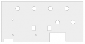
Here are the FPD files for the panels and ODAC mount I used.
Thanks for posting those!
Hey on your ODA bass boost, thinking about it some more you probably should swap out the R3 & R4 (rear RCA) and/or the R5 & R6 (front panel 3.5mm) 274R input resistors for 10K (depending on which or both of those ODA inputs you use with the 2Vrms source). Also use the 1K attenuation resistors R31 & R32 if needed to get more volume pot travel with the result. I'll put a set of all those resistors in the mail today so you can try them if you want.
The problem is overall gain. With no attenuation resistors and the original 274R input resistors you get gain settings of 1x, 2x, 4x, and 6x. Bass boost doubles those at low frequencies, so the low frequency gains would be 2x, 4x, 8x, and 12x. And therein lies the problem. With the volume pot after the gain stage it won't help with clipping. So with a 2Vrms source input, the low frequency peaks caused by the bass boost would be 4Vrms (OK), 8Vrms (clipping), 16Vrms (clipping) and 24Vrms (clipping) since the maximum swing of the gain stage with the 12.5Vdc power rails is 7.25Vrms. That sounds like pretty much what you reported. The attenuation resistors would cut the output level in half, but since they are after the gain stage too they also wouldn't help with clipping, just more rotation range on the volume pot.
By replacing those input resistors with 10K it will form a 50/50 voltage divider with the input 10K resistor, dropping the source level to 1Vrms from the 2Vrms. So now at low frequencies the bass boost would give maximum voltages of 2Vrms (OK), 4Vrms (OK), 8Vrms (clipping), and 12Vrms (clipping). The two lowest gain settings would not result in clipping, vs. just the lowest setting before. That should be OK since the upper gain switch settings are there for low output sources and yours is high output.
In addition if the 1K attenuation resistors are used all 4 of those gain stage output voltages get cut in half, giving more pot travel, if needed.
I'm glad you ran into this issue! It needs some more wording in the build instructions. I may do a cut and past from some of this post.
It is all a result of the bass boost circuit increasing gain at low frequencies, coupled with that unique O2/ODA setup of the gain stage being in front of the volume pot. You can see why I included the clipping indicator on that gain stage! Ideally, if the parts would have fit, the O2 really did need a gain stage clipping indicator.
Last edited:
I just did another thermal test....not very scientific but a test none-the-less.
I left the ODA on for three solid days to see how hot it would get being all buttoned up with no ventilation holes. No load, just on with all cables attached including headphones but no music playing...so I guess that is a load??? but no real music or tones being played.
Well the box is just barley warm to the touch, I was expecting it to be a little hotter, but it was remarkably cool, I think the heat sinking with the 2 stage regulators using the back panel and having 5 screws mating it to the chassis is doing a great job at sinking out the heat to very acceptable levels to me...
Sometimes we leave things on inadvertently so its good to know this.
Alex
Nice one, you have to remember that the whole case is actually a one big radiator, the vent holes are just to allow some flow.
This proofs that no fan is needed there at all, and the vent holes are just a nice addition if your using the heatsinks.Its a shame you dont have a simple IR thermometer,and didnt make the same test before adding the heatsink's.
Keep going
Kamil
This proofs that no fan is needed there at all, and the vent holes are just a nice addition if your using the heatsinks.Its a shame you dont have a simple IR thermometer,and didnt make the same test before adding the heatsink's.
Keep going
Kamil
- Home
- Amplifiers
- Headphone Systems
- A version of an O2 Desktop Amp (ODA)