Tuning the ODA's snubber
I've had a chance this weekend to make a test I've been wanting to for awhile. Tuning the ODA's snubber for the specific transformer being used, now that the WAU16-2400 is the pick for the standard +/-12.5Vdc power rails. Turns out changing the 110R resistor to 52R will result in being closer to critical damping with this specific transformer.
Details:
The snubber in the ODA comes right out of Hagerman's famous paper:
http://www.hagtech.com/pdf/snubber.pdf
0.01uF (C5) to lower the ringing frequency, then the series 0.068uF + 110R pair (C8, R13) to damp what is left.
The rest comes out of Mark Johnson's excellent Quasimodo thread:
http://www.diyaudio.com/forums/powe...sformer-snubber-using-quasimodo-test-jig.html
As mark points out, a person could go to a lot of effort and math measuring the leakage inductance of the specific transformer winding and plugging it in the equations. Or...simply replace the 110R with a pot, as Mark did, and adjust for critical damping. Then read the value off the pot. Simple and easy! In my case I used a 500R linear 25 turn taper. I think Mark used a 1K in his writeup.
My appologies upfront for the fuzzy photos below. I should have had the room lights on instead of just relying on the scope screen's brightness.
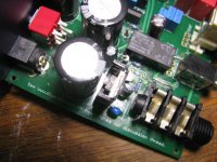
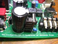
The scope is across one of the ODA's power rectifier diodes, D1.
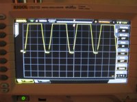
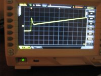
* The first photo shows the transformer's secondary leakage inductance ringing in the lower right corner of each half-cycle, that small part that fades out at this level of resolution. This is with the orignal 110R resistor.
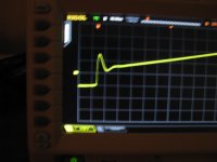
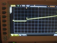
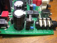
* The next photo is a closeup of the ringing with the scope's timebase stretched out. This is still the original 110R resistor. I can see the ringing dying out after one cycle. Not bad, but we can probably do better.
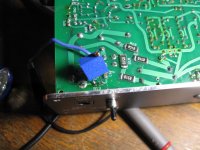
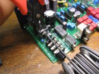
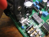
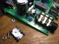
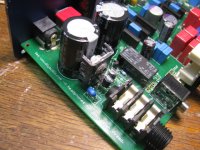
* The next photo shows the test setup, with the 500R linear trimpot soldered onto the SMD pads where the 110R R13 used to go. The blue wire is going to the end-munted end of D1 for the scope probe. I pre-set the trimpot to 110R on that side so it would start out the same as the original resistor. I've soldered the pot directly on the board like this to keep from introducing any additional inductance or capacitance from using wire leads.
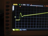
* The next waveform shows pretty close to critical damping at 52R. For each of these I unsoldered the pot, measured it, then soldered it back in. Note I've increased the vertical scale on the scope from the first two pictures to show the ringing more clearly.
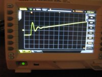
* The next waveform is with the pot in the other direction at 190R. Clearly we have ringing! I count three cycles before it damps out.
* Next I just turned the pot until the waveform was damped inone cycle and measured the pot: 102R. Nearly the same as the 110R.
* The final waveform is back to the original 110R resistor.
If you use a different transformer than the 16Vac 2.4A in the BOM and have access to a scope, just use this procedure to tune the snubber. I would suspect though that most transformers in this general voltage and amperage range will be snubbed adequately by something in the 52R range. 51R or 49.9R would be standard values.
I've had a chance this weekend to make a test I've been wanting to for awhile. Tuning the ODA's snubber for the specific transformer being used, now that the WAU16-2400 is the pick for the standard +/-12.5Vdc power rails. Turns out changing the 110R resistor to 52R will result in being closer to critical damping with this specific transformer.
Details:
The snubber in the ODA comes right out of Hagerman's famous paper:
http://www.hagtech.com/pdf/snubber.pdf
0.01uF (C5) to lower the ringing frequency, then the series 0.068uF + 110R pair (C8, R13) to damp what is left.
The rest comes out of Mark Johnson's excellent Quasimodo thread:
http://www.diyaudio.com/forums/powe...sformer-snubber-using-quasimodo-test-jig.html
As mark points out, a person could go to a lot of effort and math measuring the leakage inductance of the specific transformer winding and plugging it in the equations. Or...simply replace the 110R with a pot, as Mark did, and adjust for critical damping. Then read the value off the pot. Simple and easy! In my case I used a 500R linear 25 turn taper. I think Mark used a 1K in his writeup.
My appologies upfront for the fuzzy photos below. I should have had the room lights on instead of just relying on the scope screen's brightness.
The scope is across one of the ODA's power rectifier diodes, D1.
* The first photo shows the transformer's secondary leakage inductance ringing in the lower right corner of each half-cycle, that small part that fades out at this level of resolution. This is with the orignal 110R resistor.
* The next photo is a closeup of the ringing with the scope's timebase stretched out. This is still the original 110R resistor. I can see the ringing dying out after one cycle. Not bad, but we can probably do better.
* The next photo shows the test setup, with the 500R linear trimpot soldered onto the SMD pads where the 110R R13 used to go. The blue wire is going to the end-munted end of D1 for the scope probe. I pre-set the trimpot to 110R on that side so it would start out the same as the original resistor. I've soldered the pot directly on the board like this to keep from introducing any additional inductance or capacitance from using wire leads.
* The next waveform shows pretty close to critical damping at 52R. For each of these I unsoldered the pot, measured it, then soldered it back in. Note I've increased the vertical scale on the scope from the first two pictures to show the ringing more clearly.
* The next waveform is with the pot in the other direction at 190R. Clearly we have ringing! I count three cycles before it damps out.
* Next I just turned the pot until the waveform was damped inone cycle and measured the pot: 102R. Nearly the same as the 110R.
* The final waveform is back to the original 110R resistor.
If you use a different transformer than the 16Vac 2.4A in the BOM and have access to a scope, just use this procedure to tune the snubber. I would suspect though that most transformers in this general voltage and amperage range will be snubbed adequately by something in the 52R range. 51R or 49.9R would be standard values.
Attachments
Last edited:
ODA transformer solution for Europe
A new EU energy saving directive has apparently started that bans all non-switchmode wall bricks. A way around that is just box up a torroidal transformer yourself. Power line plug in one end (IEC jack) with fuse and switch, then a cable with a 2.1mm barrel plug out the other to the ODA. Make sure the top of the case, if metal, doesn't touch the top of the transformer or you will get a shorted turn. If the case is metal be sure to connect the incoming earth ground wire to the case. If not metal, then ground any exposed metal parts like the bolt going through the torroidal transformer.
No real need for a power line filter on the transformer primary since the ODA does all that on the secondary side. The ODA is expecting just a plug-in wall transformer.
Here is a transformer at Farnell that may do the job. It has both 115Vac and 230Vac primaries, with two 9Vac secondaries that can be put in series to get 18Vac at 2.78A:
MCTA050/09 - MULTICOMP - TRANSFORMER, 50VA, 2 X 9V | Farnell UK
Farnell # 9530355. The current is higher than needed but it will stay relatively cool at full load. They don't show a secondary combination that would produce 16Vac. Less than 16Vac with the ODA isn't advised given the two stages of voltage regulators.
Last edited:
If anyone is interested I can have a big variet of toroidal transformers starting with 230/16.5v 2a, 17v,18v ect up to 24v with different "A" in a range of 2-2.4A
That 16.5Vac 2A would be perfect!
Heat sink for IC11
kamilgd - that transformer is a nice find! Very compact. At that size it may very well fit inside one of the box enclosures cases, but I would still recommend putting it an a separate case from the ODA. Less chance of magnetic fields coupling into things. Essentially just wire it up like it is a wall transformer, with the power cord in one side (fuse highly recommended) and a cord with a 2.1mm barrel plug out the other end. I see those pre-molded 2.1mm cords with stripped leads on the other end available at a bunch of places.
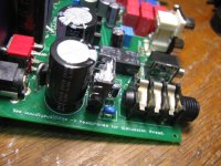
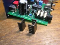
Alex - my package from Mouser arrived today with a big pile of assorted TO-220 heat sinks. Below are two candidates that will work. The only difference between the two is the length of the side fins. The one with the shorter fins is an Aavid Thermalloy 577002B00000G, Mouser # 532-577002B00. That is the one I'm going to be adding to the BOM. I've secured it with a M3 (metric 3mm) 6mm long stainless button head bolt and nut from boltdepot.com. Going forward I'm going to include both in that ODA hardward kit with the other other screws. For now I'll send the heatsinks and bolt/nut out no charge to everyone building the V2.0 ODA right now.
The other heat sink with the longer fins is an Aavid Thermaloy 577102B00000G, Mouser #532-577102B00. The fins do clear the big capacitor if the the regulator is straight up and down. That capacitor is rated at 105C by the way, which is 220 degrees F - it isn't going to care about the proximity of the heat sink in either case. But the shorter fins will do the job just fine so that's what I'm going to run with. If someone decides to use the longer fin heatsink you might want to put a thin piece of double-stick foam (the stuff used for picture mounting) between the end of the IC11 bolt and the big capacitor to keep them spaced a bit for air flow and to prevent any chance of the fins rubbing their way through the capacitor sleeving over the years and making electrical contact with the cap.
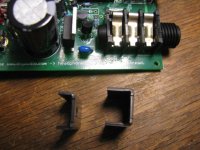
I was going to use that lockwasher in the photo but gave up.") Not needed and just one more thing to align. It would probably require a 8mm long bolt too for a lockwasher. Works fine just to hold the nut on the back with pliers while the bolt is turned with the M2 allen wrench from the other side. For the folks here in the US, you can get that metric Allen wrench set for $1.60 at any Harbor Freight tool store.
Not needed and just one more thing to align. It would probably require a 8mm long bolt too for a lockwasher. Works fine just to hold the nut on the back with pliers while the bolt is turned with the M2 allen wrench from the other side. For the folks here in the US, you can get that metric Allen wrench set for $1.60 at any Harbor Freight tool store.
As for how well it works, with the heatsink attached it is warm but I can hold it indefinitely now with no problem. This is with the 169R resistor change too.
kamilgd - that transformer is a nice find! Very compact. At that size it may very well fit inside one of the box enclosures cases, but I would still recommend putting it an a separate case from the ODA. Less chance of magnetic fields coupling into things. Essentially just wire it up like it is a wall transformer, with the power cord in one side (fuse highly recommended) and a cord with a 2.1mm barrel plug out the other end. I see those pre-molded 2.1mm cords with stripped leads on the other end available at a bunch of places.
Alex - my package from Mouser arrived today with a big pile of assorted TO-220 heat sinks. Below are two candidates that will work. The only difference between the two is the length of the side fins. The one with the shorter fins is an Aavid Thermalloy 577002B00000G, Mouser # 532-577002B00. That is the one I'm going to be adding to the BOM. I've secured it with a M3 (metric 3mm) 6mm long stainless button head bolt and nut from boltdepot.com. Going forward I'm going to include both in that ODA hardward kit with the other other screws. For now I'll send the heatsinks and bolt/nut out no charge to everyone building the V2.0 ODA right now.
The other heat sink with the longer fins is an Aavid Thermaloy 577102B00000G, Mouser #532-577102B00. The fins do clear the big capacitor if the the regulator is straight up and down. That capacitor is rated at 105C by the way, which is 220 degrees F - it isn't going to care about the proximity of the heat sink in either case. But the shorter fins will do the job just fine so that's what I'm going to run with. If someone decides to use the longer fin heatsink you might want to put a thin piece of double-stick foam (the stuff used for picture mounting) between the end of the IC11 bolt and the big capacitor to keep them spaced a bit for air flow and to prevent any chance of the fins rubbing their way through the capacitor sleeving over the years and making electrical contact with the cap.
I was going to use that lockwasher in the photo but gave up.
Not needed and just one more thing to align. It would probably require a 8mm long bolt too for a lockwasher. Works fine just to hold the nut on the back with pliers while the bolt is turned with the M2 allen wrench from the other side. For the folks here in the US, you can get that metric Allen wrench set for $1.60 at any Harbor Freight tool store.As for how well it works, with the heatsink attached it is warm but I can hold it indefinitely now with no problem. This is with the 169R resistor change too.
Attachments
-
 IMG_2723.JPG193.3 KB · Views: 63
 -
 IMG_2722.JPG182 KB · Views: 78
 -
 IMG_2721.JPG215.9 KB · Views: 82
 -
 IMG_2720.JPG193.1 KB · Views: 81
 -
 IMG_2718.JPG203.4 KB · Views: 70
 -
 IMG_2717.JPG170.6 KB · Views: 73
 -
 IMG_2716.JPG209.5 KB · Views: 75
 -
 IMG_2715.JPG192.2 KB · Views: 69
 -
 IMG_2714.JPG199.1 KB · Views: 68
 -
 IMG_2724.JPG227.5 KB · Views: 68
Last edited:
Ok heatsink on IC11, fits perfectly and R13 has been updated....playing for a few hours now, no issue and sounds very, very nice.....time to button it up !!
Alex
Good progress!
Revised BOM and Build Instructions posted, + panel
I've just posted a revised BOM and Build Instructions for this ODA project, revision date today 6/1/2014, at the Google Drive link in post #1.
Thanks goes out to dace again for spotting another one! R22 & R23, the optional 3K bass boost SMD resistors, were left off the BOM entirely. I have those added now and marked in yellow background now to show they are optional. For R23 & R24 I've marked the 3K alternate, which goes with bass boost, in green. And I've marked the two optional bass boost caps in yellow.
In the build instructions I've added additional wording in a couple of places to note that if you are using bass boost, R22 - R25 all become 3K, BUT R22 & R23 are SMD 3K resistors while R24 & R25 are through hole 3K, as per the new BOM.
I've added the heatsink and bolt/nut for IC11 to the BOM, along with the 169R set resistor for IC11 for the +/-12.5Vdc rails and the new 52.3R snubber resistor R13 that goes with the 16Vac 2.4A transformer.
I've picked a standard transformer now in the BOM for the optional higher voltage +/-15Vdc build for 300R and up only headphones. It will be the 24Vac 1A unit. 20Vac is really all that is needed, but the 24Vac 1A is $11.95 at Mouser. The 20Vac transformers jump from 500mA to 2000mA and the price for the 2A is $30. The currents involved are a lot less with the +/-15vdc power rail build than the +/-12.5Vdc build since the headphones are limited to 300R and up. So that extra 4 volts for the 24Vac transformer won't cause all that much more back panel heating.
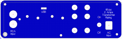
Finally I'm working on the revised backpanel this week. It may wind up more or less with two rows of vent holes and the USB hole for the ODAC.
I've just posted a revised BOM and Build Instructions for this ODA project, revision date today 6/1/2014, at the Google Drive link in post #1.
Thanks goes out to dace again for spotting another one!
R22 & R23, the optional 3K bass boost SMD resistors, were left off the BOM entirely. I have those added now and marked in yellow background now to show they are optional. For R23 & R24 I've marked the 3K alternate, which goes with bass boost, in green. And I've marked the two optional bass boost caps in yellow. In the build instructions I've added additional wording in a couple of places to note that if you are using bass boost, R22 - R25 all become 3K, BUT R22 & R23 are SMD 3K resistors while R24 & R25 are through hole 3K, as per the new BOM.
I've added the heatsink and bolt/nut for IC11 to the BOM, along with the 169R set resistor for IC11 for the +/-12.5Vdc rails and the new 52.3R snubber resistor R13 that goes with the 16Vac 2.4A transformer.
I've picked a standard transformer now in the BOM for the optional higher voltage +/-15Vdc build for 300R and up only headphones. It will be the 24Vac 1A unit. 20Vac is really all that is needed, but the 24Vac 1A is $11.95 at Mouser. The 20Vac transformers jump from 500mA to 2000mA and the price for the 2A is $30. The currents involved are a lot less with the +/-15vdc power rail build than the +/-12.5Vdc build since the headphones are limited to 300R and up. So that extra 4 volts for the 24Vac transformer won't cause all that much more back panel heating.
Finally I'm working on the revised backpanel this week. It may wind up more or less with two rows of vent holes and the USB hole for the ODAC.
Attachments
Last edited:
Looks like 4 holes on top of the board and 2 below the board.
Interesting....
Alex
Yeah the ODA PC board will act like an air flow divider in the box. So I figure a couple of holes below the board level and a few above.
So I completed my first box earlier today and have been listening to it for a few hours with various cans, and overall am loving it so far!
Huge thanks to agdr for the great design work, and for being so helpful with updating build instructions on the fly as I hit things You made being a guinea pig painless.
Image gallery:
ODA - Imgur
I think the black anodized panels came out nicely.
Build notes:
- used default +/-12.5Vdc build with 16Vac 2.4A suppy
- omitted preamp section, front RCA out, and Zobel network
- created a custom mounting board for an ODAC (see below)
- added variable gain
- DC offset per channel <50uV off the bat
- no attenuation resistors used
- uses all the latest recommended parts (snubber resistor, etc.)
- thankfully didn't accidentally sneeze and lose any SMD parts - those 0603 packages are tiny! I find Cardas Quad eutectic solder great for small parts
- added pin jumpers for the optional bass boost - e.g. http://i.imgur.com/B9IHwh5.jpg
ODAC mounting:
I broke out the calipers and made a custom mounting board for the ODAC to slide into the B4-080 enclosure above the ODA board, with screw holes, ventilation, and wiring holes for a couple options including using a 3P KK .100" KK right angle header (which fits perfectly and also helps prevent the ODAC from ever contacting the case) to wire it up, to help make it modular Since the rear RCA plugs and C11/C12 electrolytic caps were too tall I also added cutouts for those. I put the ODAC location over the regulators for similar reasons to those agdr later mentioned.
It cost a bit more to have FPE cut it out than to just use a blank board, but it definitely looks nice and made it really easy to mount. It was also maybe a bit of a risk using acrylic due to possible noise and thermal expansion but at least subjectively it seems fine.
Mounting board layout: http://i.imgur.com/DEQHa2V.png
Panels:
I designed and ordered custom panels before agdr posted the updated ones with the vents, so my vents look a bit different. I also added a cutout for a top-mounted ODAC in the back.
Front panel: http://i.imgur.com/K5P7822.jpg
Rear panel: http://i.imgur.com/ydEmiuG.jpg
If anyone's wondering about the bolts on the rear panel being backward, it's because I had a bunch of TO-220 mounting kits left over from an AMB stack I just put together I might switch them to screws going the other direction at some point, but I actually sort of like how they look this way.
Rear panel is warm but not overly so after running it for a couple hours, but you can definitely feel some warm air coming out of the vents too so it seems like they were a good idea.
Listening impressions:
Haven't done any blind or A/B testing or anything yet, but subjectively the amp sounds great to me so far in the default config fed by an ODAC. Holds up well across classical, rock, and electronic. Very clean and transparent. Completely black background with no noise. So far have spent some time with HD 650s, Mad Dog orthos, Klipsch X10 IEMs, and some old Denon AH-D1001Ks to try a range of different things.
HD650s: ODA sounds great with these - felt very smooth and transparent. No problem driving them - half volume on 2x gain is pretty loud.
Mad Dogs: clarity/detail was great with these even with fast tracks. So far I'd say it's actually maybe a better pairing than with a Schiit Modi/Magni since I can find the Mad Dog's highs a bit too harsh using the M&M, but no such problems with the ODA. Haven't tried vs. the β22 yet
Issues:
- Couldn't test the bass boost with some headphones in the default config, e.g. power-hungry planar magnetics: it would start to clip when playing low frequencies (maybe ~ <300Hz) even on low gain and low volume. Had to disable it
- Very minor board layout point: it would have been nice if JP1,JP4,JP5 (rear RCA jumpers) were evenly spaced so you could use a standard 6P header, or if there could have been enough room to squeeze in a Molex header to make wiring inputs like an ODAC more modular
Huge thanks to agdr for the great design work, and for being so helpful with updating build instructions on the fly as I hit things
You made being a guinea pig painless.Image gallery:
ODA - Imgur
I think the black anodized panels came out nicely.
Build notes:
- used default +/-12.5Vdc build with 16Vac 2.4A suppy
- omitted preamp section, front RCA out, and Zobel network
- created a custom mounting board for an ODAC (see below)
- added variable gain
- DC offset per channel <50uV off the bat
- no attenuation resistors used
- uses all the latest recommended parts (snubber resistor, etc.)
- thankfully didn't accidentally sneeze and lose any SMD parts - those 0603 packages are tiny! I find Cardas Quad eutectic solder great for small parts
- added pin jumpers for the optional bass boost - e.g. http://i.imgur.com/B9IHwh5.jpg
ODAC mounting:
I broke out the calipers and made a custom mounting board for the ODAC to slide into the B4-080 enclosure above the ODA board, with screw holes, ventilation, and wiring holes for a couple options including using a 3P KK .100" KK right angle header (which fits perfectly and also helps prevent the ODAC from ever contacting the case) to wire it up, to help make it modular
Since the rear RCA plugs and C11/C12 electrolytic caps were too tall I also added cutouts for those. I put the ODAC location over the regulators for similar reasons to those agdr later mentioned.It cost a bit more to have FPE cut it out than to just use a blank board, but it definitely looks nice and made it really easy to mount. It was also maybe a bit of a risk using acrylic due to possible noise and thermal expansion but at least subjectively it seems fine.
Mounting board layout: http://i.imgur.com/DEQHa2V.png
Panels:
I designed and ordered custom panels before agdr posted the updated ones with the vents, so my vents look a bit different. I also added a cutout for a top-mounted ODAC in the back.
Front panel: http://i.imgur.com/K5P7822.jpg
Rear panel: http://i.imgur.com/ydEmiuG.jpg
If anyone's wondering about the bolts on the rear panel being backward, it's because I had a bunch of TO-220 mounting kits left over from an AMB stack I just put together
I might switch them to screws going the other direction at some point, but I actually sort of like how they look this way.Rear panel is warm but not overly so after running it for a couple hours, but you can definitely feel some warm air coming out of the vents too so it seems like they were a good idea.
Listening impressions:
Haven't done any blind or A/B testing or anything yet, but subjectively the amp sounds great to me so far in the default config fed by an ODAC. Holds up well across classical, rock, and electronic. Very clean and transparent. Completely black background with no noise. So far have spent some time with HD 650s, Mad Dog orthos, Klipsch X10 IEMs, and some old Denon AH-D1001Ks to try a range of different things.
HD650s: ODA sounds great with these - felt very smooth and transparent. No problem driving them - half volume on 2x gain is pretty loud.
Mad Dogs: clarity/detail was great with these even with fast tracks. So far I'd say it's actually maybe a better pairing than with a Schiit Modi/Magni since I can find the Mad Dog's highs a bit too harsh using the M&M, but no such problems with the ODA. Haven't tried vs. the β22 yet
Issues:
- Couldn't test the bass boost with some headphones in the default config, e.g. power-hungry planar magnetics: it would start to clip when playing low frequencies (maybe ~ <300Hz) even on low gain and low volume. Had to disable it
- Very minor board layout point: it would have been nice if JP1,JP4,JP5 (rear RCA jumpers) were evenly spaced so you could use a standard 6P header, or if there could have been enough room to squeeze in a Molex header to make wiring inputs like an ODAC more modular
Last edited:
So I completed my first box earlier today and have been listening to it for a few hours with various cans, and overall am loving it so far!
Congratulations on your build!! That looks absolutely terrific.
I like how the black turned out. Excellent work on that ODAC addition too! Kamilgd has been eager to do more panel work for that and I haven't had the time yet to make measurements. Hey please let us know if you would be willing to either sell those panels and your ODAC mounting board over in the vendor forum, or post the CAD dimensions. One way to the other I know a lot of work went into getting it right. I'll bet several folks would be interested in both. That was a good idea having FPE cut the mounting board. It would probably be hard to get the cuts and holes exactly right with home measurements and drilling. I see that Seeed Studio also has a laser cutting service that I've been meaning to look into.
As far as I know you are the first to integrate the ODAC and ODA!
Good point about the bass boost. If the headphones involved are already using more than half of the 7.25Vrms available swing, then the bass boost would come along and double that at low frequencies, causing clipping. At least the ODA has a clipping light to let people know that is happening, unlike the O2 headamp. What is the impedance and sensitivity of the headphones that clip? If they are 300R or above they may be a candidate for the +/-15Vdc rail version. That would supply about 3Vrms more voltage swing. Another thought is to back the boost off from 3dB to 1.5dB.
Also good thoughts about the molex connectors for the RCA jack! I'll add that to my list of things to look at for the next board run.
And a big thanks again for helping root out several issues in the build instructions.
Dace...
Congrats on your ODA!!
It looks really nice!!
I am enjoying mine as well, I did a set of listening tests and it was impossible for me to tell the differences between the O2 and the ODA.
I am using Beyer T90's, DT1350's and AKG Q701 at the moment. The Beyer T90s and the ODA are superb!!
Alex
Congrats on your ODA!!
It looks really nice!!
I am enjoying mine as well, I did a set of listening tests and it was impossible for me to tell the differences between the O2 and the ODA.
I am using Beyer T90's, DT1350's and AKG Q701 at the moment. The Beyer T90s and the ODA are superb!!
Alex
Hey please let us know if you would be willing to either sell those panels and your ODAC mounting board over in the vendor forum, or post the CAD dimensions.
Sure, I want to make one or two minor tweaks then I'll post the FPD versions soon.
What is the impedance and sensitivity of the headphones that clip?
I might try the +/-15V version next. The HD650s started clipping fairly low (300 ohm, 103 dB/mW) but my pair of Mad Dogs (modded Fostex T50RPs - 50 ohm impedance, 98 dB/mW) were surprisingly audibly clipping even lower - basically right away even at low volume.
Fyi.
My Beyer T90's are 250 ohms and the sensitivity spec is:
My Beyer T90's are 250 ohms and the sensitivity spec is:
102 dB SPL at 500 Hz at 1 mW.
1 mW is 500 mV at 250 Ω, thus 1V is 4 mW or +6 dBm into 250 Ω, so 1V gives 108 dB SPL.
I don't see any clipping at my listening levels, gain on the lowest setting.
I changed the gain to position 4 and I do see the clipping light come on at mid way volume levels (on the vol pot).
Alex
Sure, I want to make one or two minor tweaks then I'll post the FPD versions soon.
I might try the +/-15V version next. The HD650s started clipping fairly low (300 ohm, 103 dB/mW) but my pair of Mad Dogs (modded Fostex T50RPs - 50 ohm impedance, 98 dB/mW) were surprisingly audibly clipping even lower - basically right away even at low volume.
Thanks for your willingness to post your CAD files!
Something is not right there with the clipping. Lets see if we can figure out what is going on. 300ohm and 103dB/mW needs just 0.22Vrms at 95dB SPL or 2.2Vrms at 115dB SPL. Both well within the range of the ODA at +/-12.5Vdc. For the other headphone, 50ohm at 98dB/mW is 0.16Vrms at 95dB SPL or 1.53Vrms at 115dB SPL, also both well within range for the ODA at 12.5Vdc. The current requirements for both are also well within range. You should be able to drive both of those headphones well above the "too loud to listen to" range with a standard +/-12.5Vdc ODA build. I'm wondering if one of the output NJM4556A chips might be bad.
Is the clipping light coming on in either case, or is it all audible? Do you have access to a scope to see the output waveform?
- Home
- Amplifiers
- Headphone Systems
- A version of an O2 Desktop Amp (ODA)