The ODA works perfectly with HE500 and HE6 up to 118dB and 113dB
I'm posting a copy of a PM below that I just sent Alex in response to a good question he had. A fellow on another forum was asking about the ODA powering the HE500 and notoriously hard-to-drive HE6. Turns out the answer is no problem at all for the ODA. I've added a folder to the V2.0 ODA Google Drive link called "Headphones vs. the ODA" with the spreadsheets and a README with all the details. I also show in there why NwAvGuy's O2 amp is past its current handling capabilities with these headphones at the higher power levels, with only 2 NJM4556A output chip sections per channel vs. 6 NJM4556AL sections for the ODA on each channel..
_________________________________________________________
So here is your answer about the HE500 and HE6. The ODA will not only power both perfectly with the standard +/-12.5Vdc power rails, they will do so all the way up to 118dB and 113dB, respectively. And those were just the power levels that broke the spreadsheet. Nobody should be listening to headphones at those levels anyway! See the hearing damage chart at the bottom of the fellow's spreadsheet.
I have created a new folder at the V2.0 ODA Google Drive link called "Headphones vs. the ODA". Here is a direct link to it:
https://drive.google.com/folderview?id=0B67cJELZW-i8SXZrcktvTGl2Y28&usp=sharing
In there I have used a nice power calculation spreadsheet that was posted on Head-Fi back in December. See the README file in that folder. It has a link to that post with the sheet and links to the specification pages for the HE500 and HE6. They are 38 ohm at 89dB/mW sensitivity, and 50 ohm at 83.5dB/mW respectively. Note that per mW is assumed, both by the fellow who created the spreadsheet and by me, since the manufacturer does not say whether per mW or per V. Per mW is the older and more standard measure so its a good bet.
For more normal levels I have also included sheets for both at 95dB.
Only the 113dB power level with the HE6 is coming near the using the full 7.25V(rms) swing of the ODA with the +/-12.5Vdc rails, at 6.67V(rms). The current is still a no-brainer for the ODA, divided by 6 for the 6 output chips.
So.. these kind of headphones are exactly what the ODA eats for lunch.
Also please note that the +/-15Vdc power rails should not be used with either headphone. +/-12.5Vdc does the job as per the charts. The output chips could overheat at the higher voltages. Those are only for 300R and 600R cans.
Last edited:
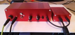
Well I finally got the front panel almost completed, still needs some minor work, labeling etc..
But it looks pretty good so far...
I have my AKG Q701's plugged into the 1/4 jack and the Beyer T90's in the 3.5 mm jack.
Both playing just fine.
note: Diana Krall never sounded so good!! LOL!
Alex
But it looks pretty good so far...
I have my AKG Q701's plugged into the 1/4 jack and the Beyer T90's in the 3.5 mm jack.
Both playing just fine.
An externally hosted image should be here but it was not working when we last tested it.
note: Diana Krall never sounded so good!! LOL!
Alex
Attachments
Last edited:
Sure I can share with the CAD files with the community
Thank you! I really like how your panels look. I was just looking back through some posts and I don't think I ever answer your question on where to get panels made.
I've used Front Panel Express:
Front Panel Express:*Front Panel Design Software and CAD Conversion Service
and cam-expert.com (which can make use of the same .fpd files):
Front panels manufactured by the specialists at Cam Expert
Both say that the blank front panels that come with the B4-080 cases can be mailed to them to be used. That gets you an exact color match and the edges are color-anodized that way. Both give a tiny discount for using your own blank panels, but that all gets eaten up by postage in sending them the panels. Front Panel Express is about 20% more than cam-expert, although they sometimes run 20% off specials on their Facebook page.
Both of those outfits are here in the U.S. Overseas Schaeffer AG does panels and they appear to own Front Panel Express :
Schaeffer AG: Home
I've looked into e-machine shop here in the U.S. but the price would be astronomically higher. They are more of a general purpose machine shop that would mill the entire panel, thickness and all, out of a block of aluminum. I'm still searching for a panel shop somewhere out there which can do it for less money and use the .fpd files.
I will definitely send you those USB port measurements when I have them locked down.
Last edited:
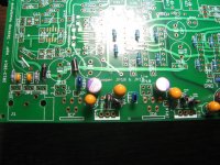
IMPORTANT: D4 IS IN THE WRONG WAY IN MY PHOTOS
A big thanks goes out to dace for just discovering the mother of all screw-ups in one of my build photos, below. See how the "flying lead" on D4, the diode in the middle front of IC4, is oriented toward the IC4 chip? That is wrong! The Part ID diagram out at the V2.0 Google Drive project link shows it well. That hole is JP11 where the white wire carrying the power input should go. That diode lead should isntead go the hole just left of D4 (the hole that has the last 11 of the JP11 silk screen cut off), which is where I put the white wire.
In a truely lucky turn of events this mis-wire didn't smoke anything, which is why I didn't discover it in testing. The mis-wire ran the incoming power directly to the LT3015 LDO, which still produced the correct output voltage. The LT3015 has a 30V maximum input though. Part of the purpose of the pre-regulators (which are rated at 37Vdc input) is to reduce the voltage to less than 30 for the LDOs. But in my case I used 20Vac and 16vac transformers for testing, which equate to 23Vdc and 28Vdc peak, under the 30Vdc chip maximum. And on Alex's board, which I can see I also mis-wired from the photos, he is using the new 16Vac 2.4A transformer. So the LT3015 survived just fine.
As for why the LM337 survived, the mis-wire fed incoming power to the output of the chip rather than the input. But luckily the mis-wire left the input floating, and the adjust pin doesn't care as long as the polarity from output to ground is correct. So the LM337 also survived, it just was sitting there not doing anything.
Hopefully only my board and Alex' go snagged by this so far. Let me know...
Clearly I'm going to have to improve the labelling on JP11 on the next batch of boards. In the build instructions I have a step to check that pre-regulator voltage by using the test point JP17. But I skipped that test on my own builds. If I hadn't it would have detected the problem.
Attachments
Last edited:
Well converting the .fpd file into any other file isnt a big problem at the end of the day, its just a matter of finding the cheapest manufacturer. As you know ordering 1-2panels is just to expensive and im looking for something like a batch of 20-100 panels just to cut the price per panel, and sell them to all interested, I dont need to make any profit from it as DIY is just my hobby like for most of us.
Well converting the .fpd file into any other file isnt a big problem at the end of the day, its just a matter of finding the cheapest manufacturer. As you know ordering 1-2panels is just to expensive and im looking for something like a batch of 20-100 panels just to cut the price per panel, and sell them to all interested, I dont need to make any profit from it as DIY is just my hobby like for most of us.
I would be in for some of the panels!
Question,
Once I correct this will this affect the offset voltage settings?
GOOD CATCH !! Dace!
Thanks for letting us know ASAP agdr...
I will correct this pm and post results!!!
Alex
(smiling here!!)
Nope, won't affect anything. Both LDOs were still producing the correct voltages. The only effect at all was that the LT3015 was working harder than it normally would, but still within specs.
.....and if I had taken the time to read agdr's theory well...its all pretty much explained there!!
"The Linear Technology (LT) low noise low dropout (LDO) regulators unfortunately have rather low maximum input voltages. 20Vdc for the LT3015 negative regulator and 30Vdc for theLT1963A positive regulator. So some sort of voltage dropping circuit needs to be added in front of the regulators. In this design I’ve used traditional non-low dropout LM317 and LM337 chipsas pre-regulators outputting +/-18.5Vdc to feed the LT chips. Not only does that solve the problem of the low input voltage on the LT chips, but provides a full pre-regulation ripple and noise reduction going into the LT chips. The result is extremely low ripple and noise out of the final LT regulators. So low, in fact, that it is likely to be lower than what would even matter given the noise factors in the rest of the chips. In other words, likely overkill, but it comes for free since the incoming LT chip voltage had to be reduced anyway.
The pre-regulators serve a second purpose of dissipating about half of the heat generated when using a 24Vac transformer. The ideal transformer for this amp would be about 20Vac, but those are hard to find. 24Vac transformers are much more common but produce about 6Vdc more than is needed which has to be burned off in heat. The LM and LT regulators both have built in temperature safe area cut-outs in case the chips overheat. By spreading out the dissipation like this it helps insure SOA cutoff won’t occur, even with 24Vac transformers."
Alex
Alex - yep, all of that. I still haven't had a chance to go back through that theory section and adjust the voltages to match the new +/-12.5Vdc rails.
By the way, a big credit here goes out to jcx and Mark Johnson for talking me out of how I was going to arrange the voltage regulators. I was going to set the pre-regulators up as "tracking" pre-regulators that wrap around the LDO chip, similar to what is in the Jung Super-regulator. The tracking arrangement seems to have a big advantage at first blush in that it keeps a constant voltage across the LDO, allowing it to focus on regulating the load. The line regulation is all relagated to the tracking pre-regulator.
BUT.. as jcx and Mark correctly point out, that tracking arrangement also provides a reverse path for circuit noise to make it back to the error amplifier of the voltage pre-regulator. By simply cascading the voltage regulators here that can't happen, or at least the effect is greatly reduced. You simply wind up with cascaded ripple reduction.
The voltage reduction function of the pre-regulators is especially important for the positive LDO, the LT1963A, which is rated at only 20V input vs. 30V for the LT3015. If I had made that same wiring mistake on the postive voltage regulator side it would have smoked the LT1963A. Linear Technology essentially calls those two a complimentary pair in the data sheets. Lol! That is about as "complimentary" as LT gets with things it seems. At least the output noise figures and other metrics of the two chips are more-or-less similar.
All of this is part of why I'm expecting some good things to result from the dScope noise floor measurements. I haven't submitted an ODA to John at JDS yet as I'm still messing with some measurements, but soon.
I still haven't had a chance to go back through that theory section and adjust the voltages to match the new +/-12.5Vdc rails.By the way, a big credit here goes out to jcx and Mark Johnson for talking me out of how I was going to arrange the voltage regulators. I was going to set the pre-regulators up as "tracking" pre-regulators that wrap around the LDO chip, similar to what is in the Jung Super-regulator. The tracking arrangement seems to have a big advantage at first blush in that it keeps a constant voltage across the LDO, allowing it to focus on regulating the load. The line regulation is all relagated to the tracking pre-regulator.
BUT.. as jcx and Mark correctly point out, that tracking arrangement also provides a reverse path for circuit noise to make it back to the error amplifier of the voltage pre-regulator. By simply cascading the voltage regulators here that can't happen, or at least the effect is greatly reduced. You simply wind up with cascaded ripple reduction.
The voltage reduction function of the pre-regulators is especially important for the positive LDO, the LT1963A, which is rated at only 20V input vs. 30V for the LT3015. If I had made that same wiring mistake on the postive voltage regulator side it would have smoked the LT1963A. Linear Technology essentially calls those two a complimentary pair in the data sheets. Lol! That is about as "complimentary" as LT gets with things it seems. At least the output noise figures and other metrics of the two chips are more-or-less similar.
All of this is part of why I'm expecting some good things to result from the dScope noise floor measurements. I haven't submitted an ODA to John at JDS yet as I'm still messing with some measurements, but soon.
Last edited:
Thanks, I wonder why one is 20 volts and the other is 30 volts??/
That does seem odd indeed....
I cant wait for the measurements to be completed, I think this will be a "giant" step for the ODA!!
Regardless of the outcome after listening now for 10 hrs or so I am totally satisfied that the amp "sounds" very, very
good. I got so lost in the music last night which to me is one of the best compliments you can get with this stuff...
My Beyer T90's and this amp are really special to me.
Alex
Last edited:
Corrected photo of D4's installation and JP11 power feed
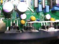
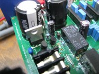
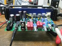
OK, the first photo below is with the D4 diode and JP11 mis-wire fixed. The negative rail power input is now going to JP11, in front of IC4, and the flying lead of D4 is going to the hole just left of it, view from the back of the PC board. Thanks again to dace for spotting this!
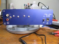
* The next photo is the current back panel design that I received back from cam-expert.com a couple of weeks ago. It really does need vent holes! I haven't had a chance to add those yet but should be able to do it this week. Or even better use kamilgd's design. Mine will just be holes - I like the circular slots he had made.
* The next photo shows the "new" R70 (the one on end) in the relay circuit section that goes with the +/-12.5Vdc power rail BOM and 24Vdc relay. It is still 3.01K, just 1/4W. If you have the larger 1/2W 3.01K that was originally in the BOM that will work just fine too. Lol - note from the lettering on the relay it is still the 48Vdc. Next step when I installed R70 was using the Hakko 808 to get the relay out and swap with the new 24Vdc unit.
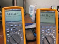
* The next one shows the voltages at the pre-regulator output test points, JP16 & JP17, +14.5Vdc and -14.36Vdc, right on the money. If I had made this test during either my build or when wiring up Alex's board - and the test is in the build instructions! - I would have discovered my wiring problem.
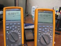
* The next photo shows the output voltage from the final LDOs, +12.52Vdc and -12.41Vdc, again right on the money. The voltage references built into the voltage regulators have a small +/- tolerance from chip to chip. The final result will usually be just slightly off from the 12.5Vdc target unless you get lucky. That is why R33 and R36 are in there as "tweak" resistors if anyone wants to get really fanatical about perfectly matched rail voltages. That miniscule voltage difference between rails won't matter a bit electrically, clipping would just hit one rail first by 100mV, but what the heck. I did some math and upping the R36 from 20R to 40R would likely bring the negative rail down to around -12.50Vdc. Easier than the math just order some extra 1206-sized SMD 0.1% resistors (1/8W or 1/4W is fine) in 10ohm increments, like 30R, 39R, 49.9R, etc and pop them in one at a time until you get where you want to be if your particular LDO chip on either rail reads a tiny bit low.
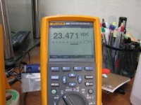
* The next photo shows the new relay regulator output voltage, +23.47Vdc here but remember referenced to the negative CRC rail, not ground. That voltage is just fine. The relay regulator target is 24Vdc and close definitely counts here. The relay is good for +/-50% of the rated coil voltage.
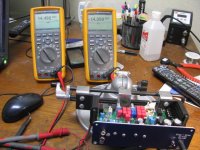
* And the final photo is playing music! Sounds great.
OK, the first photo below is with the D4 diode and JP11 mis-wire fixed.
The negative rail power input is now going to JP11, in front of IC4, and the flying lead of D4 is going to the hole just left of it, view from the back of the PC board. Thanks again to dace for spotting this! * The next photo is the current back panel design that I received back from cam-expert.com a couple of weeks ago. It really does need vent holes! I haven't had a chance to add those yet but should be able to do it this week. Or even better use kamilgd's design. Mine will just be holes - I like the circular slots he had made.
* The next photo shows the "new" R70 (the one on end) in the relay circuit section that goes with the +/-12.5Vdc power rail BOM and 24Vdc relay. It is still 3.01K, just 1/4W. If you have the larger 1/2W 3.01K that was originally in the BOM that will work just fine too. Lol - note from the lettering on the relay it is still the 48Vdc. Next step when I installed R70 was using the Hakko 808 to get the relay out and swap with the new 24Vdc unit.
* The next one shows the voltages at the pre-regulator output test points, JP16 & JP17, +14.5Vdc and -14.36Vdc, right on the money. If I had made this test during either my build or when wiring up Alex's board - and the test is in the build instructions! - I would have discovered my wiring problem.
* The next photo shows the output voltage from the final LDOs, +12.52Vdc and -12.41Vdc, again right on the money. The voltage references built into the voltage regulators have a small +/- tolerance from chip to chip. The final result will usually be just slightly off from the 12.5Vdc target unless you get lucky. That is why R33 and R36 are in there as "tweak" resistors if anyone wants to get really fanatical about perfectly matched rail voltages. That miniscule voltage difference between rails won't matter a bit electrically, clipping would just hit one rail first by 100mV, but what the heck. I did some math and upping the R36 from 20R to 40R would likely bring the negative rail down to around -12.50Vdc. Easier than the math just order some extra 1206-sized SMD 0.1% resistors (1/8W or 1/4W is fine) in 10ohm increments, like 30R, 39R, 49.9R, etc and pop them in one at a time until you get where you want to be if your particular LDO chip on either rail reads a tiny bit low.
* The next photo shows the new relay regulator output voltage, +23.47Vdc here but remember referenced to the negative CRC rail, not ground. That voltage is just fine. The relay regulator target is 24Vdc and close definitely counts here. The relay is good for +/-50% of the rated coil voltage.
* And the final photo is playing music! Sounds great.
Attachments
Last edited:
Good Morning...
Mine are 12.5 and -12.44.
I am still thinking of drilling holes for venting, and have no problem doing that but am wondering if its really needed??
In my case full buttoned up the overall case seems to be getting slightly warm but no where anything I would get worried about??
Are there any temp measurements you have done that causes us to really do venting??
All the best
Alex
Good Morning...
Mine are 12.5 and -12.44.
I am still thinking of drilling holes for venting, and have no problem doing that but am wondering if its really needed??
In my case full buttoned up the overall case seems to be getting slightly warm but no where anything I would get worried about??
Are there any temp measurements you have done that causes us to really do venting??
All the best
Alex
Alex - for your collection of headphones the venting really isn't needed. I'm just thinking in the more general case where the amp could be run near that maximum 340mA per channel. The metal case will do a good job transferring heat just the way it sits. Since your back is already attached I would probably just leave it the way it is if it were me.
In fact, that is another test I can do. I'll place a thermocouple inside and run the wire out via the gap in one of the front panel controls. It would be interesting to quantify how hot is gets without the vents, using more sensitive headphones like yours that don't pull a lot of current.
I'm glad you like the sound!
Funny I was going to tell you to post some pix of the correct wiring and the diode etc....ha!! and then you posted the pix above!! Like thinking minds!! LOL.
I agree I don't think with what I am doing I need venting....however being cautious etc I was thinking of doing it awhile back before I had it buttoned up and enclosed.
The sound to me is incredible. Yes I can't tell the difference between it and the O2 but that's a good thing.
There is a part of me that could wax endlessly in subjective terms on how great sounding it is "not" its transparent!! LOL.....but everything that has been said about the O2 transfers to the ODA and the ODA has so much more 'stuff' and the ability to customize if desired.
Question have you measured the temp on IC11 with the resistor changes? If not I will next week when I get it changed out.
Have a great Memorial Day!!
Alex
- Home
- Amplifiers
- Headphone Systems
- A version of an O2 Desktop Amp (ODA)