kamilgd - Yeah a passive vent alone would help a lot. The metal case will dissipate heat fairly well, but still a temperature difference (vs. ambient) will have to build up to drive the heat throught the case (hotter insides). With the passive vent that should result in cooler parts. In fact, that is such a good idea. I really should add a vent of some sort to the back panel I've made, or at least do a second CAD drawing option with a vent.
dace - interesting about the fan! That stuff about the air flow causing a charge buildup is real. With extremely low voltage sensing for instrumentation amps and such, probably in the 100s of nV or less with high impedance lines, the datasheets for chips mention that. Even the thermocouple effect at the solder joints starts to matter! The datasheets advise having the same number of solder joints on the inverting and non-inverting leads to cancel out that effect. And they suggest putting guard rings around the inverting and non-inverting inputs, held at a certain potential. A whole different world (of layout trouble!). But at the 30uV range with fairly low impedance lines some moderate amount of air flow should be OK.
I would suggest powering any fans from that TL783 regulator for the relay circuit (48V). That would keep any fan electrical noise fully isolated from the rest of the regulators running the audio stuff. The fan power wiring then can just be run through the AC input parts which are already noisy (1000uf filter caps, D1, D2). But it may be harder to find a 48Vdc fan. A zener diode of the proper wattage could probably be put in series to drop that 48Vdc to whatever is needed for a fan.
Also, dace and Turbon (I've already let Alex know in a PM)- there are going to be a couple of ODA part changes posted next week. I'm working on some stuff this weekend. So please hold off on any new part orders until I post that. In that posting I'm going to put that I don't want anyone to be out any money on part changes, so if anything already ordered needs to be swapped it is on me, including postage.") I'll explain more in one of my overly verbose posts next week, but in the end you will get the very best ODA amp design, with more options to cover the widest range of headphones.
I'll explain more in one of my overly verbose posts next week, but in the end you will get the very best ODA amp design, with more options to cover the widest range of headphones.
dace - interesting about the fan! That stuff about the air flow causing a charge buildup is real. With extremely low voltage sensing for instrumentation amps and such, probably in the 100s of nV or less with high impedance lines, the datasheets for chips mention that. Even the thermocouple effect at the solder joints starts to matter! The datasheets advise having the same number of solder joints on the inverting and non-inverting leads to cancel out that effect. And they suggest putting guard rings around the inverting and non-inverting inputs, held at a certain potential. A whole different world (of layout trouble!). But at the 30uV range with fairly low impedance lines some moderate amount of air flow should be OK.
I would suggest powering any fans from that TL783 regulator for the relay circuit (48V). That would keep any fan electrical noise fully isolated from the rest of the regulators running the audio stuff. The fan power wiring then can just be run through the AC input parts which are already noisy (1000uf filter caps, D1, D2). But it may be harder to find a 48Vdc fan. A zener diode of the proper wattage could probably be put in series to drop that 48Vdc to whatever is needed for a fan.
Also, dace and Turbon (I've already let Alex know in a PM)- there are going to be a couple of ODA part changes posted next week. I'm working on some stuff this weekend. So please hold off on any new part orders until I post that. In that posting I'm going to put that I don't want anyone to be out any money on part changes, so if anything already ordered needs to be swapped it is on me, including postage.
I'll explain more in one of my overly verbose posts next week, but in the end you will get the very best ODA amp design, with more options to cover the widest range of headphones.
Last edited:
well mounting a fan inside the box isn't an option so the only option would be to mount it outside, but then you loose on the esthetic, another option is to change the box for a taller one, but then you lose on portability, so passive vent is a compromise i think.
If you want the passive ventilation to have any real effect you need to pay close attention to where you place the in- and outlets. I don't know how much energy those four devices at the back need to dissipate, but by making large cut-outs in what is effectively a heat sink, you might actually make things worse.
I'm sure agdr is much more experienced with applied thermodynamics than what I am, so I won't make a fool of myself by making any suggestions.
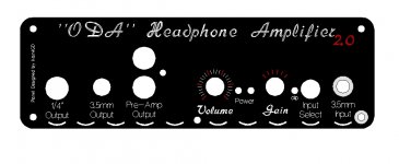
On a completely different note. In the drawings and pictures I can't seem to find holes providing for an ODAC with standoffs. Have this been considered?
There appears to be room enough.
adgr - Your 100% right, the metal case will dissipate the heat but only albo 50% of it becouse of the fact of a closed box, a lot of the heat will still sit inside generated over time of use ( and they're only generated by the Vreg's at the back ), so placing a passive vent on the metal back plate of the panel will drop the inside box temps really well, where the back panel temperature will drop only a little bit, but the vent will allow to dissipate that heat using air circulation rule, where the hot air goes up and the cooler stays down,
Infact you dont need to place any inlets in the case, becouse of this fact, as You dont need to cool the entire PCB, only dissipate the heat from the back panel, and dont let it build up in the case itself.
Limp - Im working atm on the ODAC hole, I have pm'd agdr about the right position of the micro-usb slot, so this bit will be covered in this or next release of my design,
Keep in mind that my panel design isnt 100% complete and will change for sure in 2.1
well after some thoughts i came up with such an design, still isnt 100% final but brings me few other ideas, like outside radiators mounted to the backpanel, but i need to find some nice looking ones.
Will keep updating this for you.
Kamil
Will keep updating this for you.
Kamil
Attachments
Hey good work guys on the panels and thermal considerations!
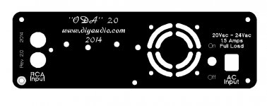
I did a surface IR temperature measurement on the O2 amplifier back panel, with a modification I posted a couple of years ago, that mounted the two O2 voltage regulators on the back panel. The temperature drop-off with distance past the regulators on each side was significant. I didn't plot it but looked like it was the typical Gaussian curve distribution. I've only done "finger measurements" on the ODA since it only gets in the warm range, not really super hot, and it feels the same. Most of the dissipation is right around the 4 regulators with pretty quick drop off after on either side. Plus in this case there will be some heat transmission to the case along the edges and mounting screws.
Good thoughts on the fan - or passive - hole blocking heat flow. Adding cross-links perpendicalar to the hole, like kamilgd has there, is probably a good idea to help the heat flow. In this instance though since the area around the hole will be cooler due to the fan air flow and/or convection air flow, I'll take a guess that things will pretty much end up a wash. Any blocked heat flow traveling sideways through the panel will more-or-less be made up by lower temperatures around the hole. If the regulator area was getting much hotter than it does then that probably wouldn't be the case, but with the current dissipation levels it should be OK.
Yeah, that back panel will radiate heat in both directions, outside the box and inside the box! A passive - or fan - vent hole is just a really good idea. The output chips dissipate quite a bit of power too. The passive radiator is an excellent idea also. The place to put it would be just below that row of 4 holes for the regulators. Something like the typical small TO-220 heat sink here:
http://www.radioshack.com/product/index.jsp?productId=2102857
but mounted sideways on the outside of the back panel. Maybe two of those end to end in fact, or just one longer one. What that would do is "bias" the heat flow to the outside of the box by lowering the thermal resistance on the back surface of the rear panel vs. the inside surface. In other words, would keep more of the heat out of the insides of the box. I would put some zinc oxide heat sink compound between the case surface and the back of that heat sink too.
Regarding the ODAC, by my measurements it should fit just fine between a card inserted in the B4-080 box top slot and the top of the case. I know that people right now install the ODAC in a similar fashion under the O2 amp PC board (insulation wrapped of course), and that has less available space. The card can just be a piece of perfboard or copper clad board cut for 80mm x 160m. Or, simply use another ODA PC board and don't solder anything on, just use it as a substrate for mounting the ODAC in the board top slot. The audio out from the ODAC can be wired into the external input holes by either the rear RCA jack or front 3.5mm jack.
I have to admit to not having an ODAC, I've been waiting for OPC'c upcomming DAC project. So I don't have one here to pull measurements from. If someone has a caliper and is willing to make some measurements, please pass them along. I probably should get an ODAC though. Lemme think about that..
I did a surface IR temperature measurement on the O2 amplifier back panel, with a modification I posted a couple of years ago, that mounted the two O2 voltage regulators on the back panel. The temperature drop-off with distance past the regulators on each side was significant. I didn't plot it but looked like it was the typical Gaussian curve distribution. I've only done "finger measurements" on the ODA since it only gets in the warm range, not really super hot, and it feels the same. Most of the dissipation is right around the 4 regulators with pretty quick drop off after on either side. Plus in this case there will be some heat transmission to the case along the edges and mounting screws.
Good thoughts on the fan - or passive - hole blocking heat flow. Adding cross-links perpendicalar to the hole, like kamilgd has there, is probably a good idea to help the heat flow. In this instance though since the area around the hole will be cooler due to the fan air flow and/or convection air flow, I'll take a guess that things will pretty much end up a wash. Any blocked heat flow traveling sideways through the panel will more-or-less be made up by lower temperatures around the hole. If the regulator area was getting much hotter than it does then that probably wouldn't be the case, but with the current dissipation levels it should be OK.
Yeah, that back panel will radiate heat in both directions, outside the box and inside the box! A passive - or fan - vent hole is just a really good idea. The output chips dissipate quite a bit of power too. The passive radiator is an excellent idea also. The place to put it would be just below that row of 4 holes for the regulators. Something like the typical small TO-220 heat sink here:
http://www.radioshack.com/product/index.jsp?productId=2102857
but mounted sideways on the outside of the back panel. Maybe two of those end to end in fact, or just one longer one. What that would do is "bias" the heat flow to the outside of the box by lowering the thermal resistance on the back surface of the rear panel vs. the inside surface. In other words, would keep more of the heat out of the insides of the box. I would put some zinc oxide heat sink compound between the case surface and the back of that heat sink too.
Regarding the ODAC, by my measurements it should fit just fine between a card inserted in the B4-080 box top slot and the top of the case. I know that people right now install the ODAC in a similar fashion under the O2 amp PC board (insulation wrapped of course), and that has less available space. The card can just be a piece of perfboard or copper clad board cut for 80mm x 160m. Or, simply use another ODA PC board and don't solder anything on, just use it as a substrate for mounting the ODAC in the board top slot. The audio out from the ODAC can be wired into the external input holes by either the rear RCA jack or front 3.5mm jack.
I have to admit to not having an ODAC, I've been waiting for OPC'c upcomming DAC project.
So I don't have one here to pull measurements from. If someone has a caliper and is willing to make some measurements, please pass them along. I probably should get an ODAC though. Lemme think about that..
Last edited:
I sent agdr a PM about heatsinking to allow for higher voltages etc...and then I re-read the above post!!
Many audio amps have rear mounted heat sinks for there power output devices etc...I was thinking of that and maybe larger or more heatsinks even if it meant a larger case might be needed for them.
Maybe some holes drilled along the back top of the case and the back bottom.....??
Alex
Many audio amps have rear mounted heat sinks for there power output devices etc...I was thinking of that and maybe larger or more heatsinks even if it meant a larger case might be needed for them.
Maybe some holes drilled along the back top of the case and the back bottom.....??
Alex
http://www.amazon.com/20mm-Aluminium-Heat-Diffusion-Cooling/dp/B0050MR8CG/ref=cm_cr_pr_sims_t
Maybe something like this mounted securely to the back panel? Just countersink holes for mount screws thru the regs or countersink the holes etc .....
hmmm
Alex
Maybe something like this mounted securely to the back panel? Just countersink holes for mount screws thru the regs or countersink the holes etc .....
hmmm
Alex
IMPORTANT: ODA BOM CHANGE TO +/-12.5Vdc -OR- +/-15Vdc RAILS
Ok, here is the update I mentioned a few days ago on what is changing with the ODA. I'm still doing some testing but I wanted to give everyone a heads-up what is coming. I have an updated BOM, schematic, "ODA vs. O2 vs. booster board" comparison, and build instructions (with just the "build options" section at the top updated so far).
What is changing is there will now be two different builds with different power supply voltages. Nothing in the layout changes. The changes are all largely a few resistors, one diode, possibly the voltage of the power transformer, and the voltage of the headphone relay. The 1K volume pot also changes from the log to the linear version of the same 9mm pot.
The "standard" build going forward will have +/-12.5Vdc rails, just slightly more than the O2 headamp's 12.0Vdc rails, but 3x more current capability of course. This build works with any headphone impedance values from 16R to 600R or more. This +/-12.5Vdc build will now use a 1K linear volume pot rather than a log pot, since the linear pot has twice the power dissipation rating as it turns out. The 1K pot will work just fine whether the attentuation resistors are used or not. The transformer will probably change to 16Vac at 2.4A (Mouser WAU16-2400) but that is one of the things I'm still testing. Anything in the 16vac - 20Vac range with adequate current for the headphone load will probably work too, and is being evaluated.
The second "optional" build is for folks who specifically have 300 ohm or 600 ohm (or higher) headphones that almost have enough volume with the O2 headamp, but not quite. This build has +/-15Vdc power supply rails and uses a 5K volume pot (linear or log taper, either is fine) again for pot power dissipation reasons. The transformer with this +/-15Vdc build remains that same as up until now, 20Vac - 24Vac. This +/-15Vdc build should only be used with 300R or higher headphones for output chip power dissipation reasons.
Note that if you have 300R or 600R headphones that are nowhere near loud enough with the O2 then the +/-15Vdc rail option here isn't likely to help. You need a lot of additional voltage swing to get adequate dynamic range on music peaks, such as AMB's b22 headamp with +/-30Vdc rails or a tube amp.
My appologies up front on the changes mid-stream here. In the previous version of the ODA I had a voltage select switch in back that selected between +/-7Vdc or +/-16vdc power supply rails to allow a wide range of headphone impedances to be used without overheating the output chips. The high voltage position was intended for high impedance phones that were not loud enough on the low voltage position. But in actual practice in speaking with some folks I came to realize that when, exactly, to use that switch wasn't clear, and at what combinations of headphone impedance and output voltage swing the lower voltage position had to be used. I eliminated the voltage select switch in this version of the ODA's schematic and layout with the intent to have two different power supply builds like this instead. That was done last year though and I completely forgot about the issue when I went back a few months ago and started updating the layout again. I just realized what had happened late last week.
I decided to reduce the maximum voltage from +/-16Vdc up until now to +/-15Vdc just to be conservative with output chip power dissipation with the 300R headphone load. The +/-15Vdc (or +/-16Vdc) power rails certainly could be used with lower impedance headphones, but the problem is that there is some maximum voltage swing past which the output chips would fry. Looking at the numbers in most cases that point would result in screamingly loud headphones so an argument could be made that +/-16Vdc rails are OK because nobody would turn their 32R or 16R headphones up that loud. But I always look at worst-case scenarios, like the headphones sitting on the table and someone cranks the volume pot without hearing the results. Then the output chips burn up. With the changes listed here to the two different power rail voltage options, and the 300R/600R restrition on the +/-15Vdc rails, there will never be any chance of overheating the output chips at any volume or gain setting level.
The other issue here, about the volume pot dissipation, is one that I completely missed to be perfectly honest. My setup here needs the attentuatioin resistors so the issue of volume pot dissipation didn't come up. It wasn't until Alex asked some good questions about jumpering the attenuation resistors for full voltage swing that I saw the problem. The good news is that the linear version of the same 1K volume pot has twice the power dissipation rating and with the +/-12.5Vdc power rails it will always stay within that power rating, even with full voltage swing with the attenuation resistors jumpered. I see linear volume pots are popular with a lot of folks, especially the guitar amp fans it seems. The sound is exactly the same with either linear or log volume pots, the difference is just how fast the volume goes up per given amount of shaft rotation.
I don't want anyone to be out any money on these changes. If you have already purchased parts that have to be changed here, PM me and I'll send you the replacements at no charge.
I am still doing some testing so best to still wait on buying any parts until Monday of next week. I just wanted to get this general change info out there as soon as possible.
Last edited:
adydula - I was looking at similar ones too, they will work, but will leave sharp edges, so pulling your hands there in a rush may cause a injury. In my little vision of the back I see one big "D" shape radiator to eliminate the injury factor, with drilled holes exacly there where the Vreg holes are and place that radiator like that, it will bring a little style to it as well.
Kamil
Kamil
GoldenboyXD - wait with your order till 2.1 release it brings few changes that are worth waiting.
Kamil
Kamil
The panels that come with the box enclosure are 53mm wide, 170 mm long. It should be easy to drill a few holes for this heat sink to easily fit on the back side.
Amazon.com: 98 x 40 x 20mm Aluminium Heat Diffusion Cooling Fin: Electronics
You can file down any sharp edges if that Is a concern...
Think I will try this in the near future..
Alex
Amazon.com: 98 x 40 x 20mm Aluminium Heat Diffusion Cooling Fin: Electronics
You can file down any sharp edges if that Is a concern...
Think I will try this in the near future..
Alex
16Vac 2.4A vs. 16Vac 1A transformer for +/-12.5Vdc rails
Here is the verdict about which transformer is needed for the new +/-12.5Vdc "standard" power rails in the ODA - it is the larger 16Vac 2.4amp WAU16-2400 unit at Mouser. Their 20Vac 2A transformer could be used too, the WAU20-2000, but they have that priced at nearly double for some reason. The back panel would also get hotter with the 20Vac unit since that extra 4Vac would all be burned off by the pre-regulators.
BTW, I forgot to say in the previous post where that extra 0.5 volts in the +/-12.5Vdc power rails comes from. That really is not an attempt to just one-up NwAvGuy's +/-12.0Vdc power rails in his O2 headamp. The inline SIP package of the NJM4556AL chips is rated at 100mW more, 800mW, vs. the DIP8 package (NJM4556A) at 700mW in the O2. So that extra 0.5 volts is using 20mW of the extra 100mW package power dissipation in each chip from quiescent (idle) current, leaving 80mW more for signal output per chip.
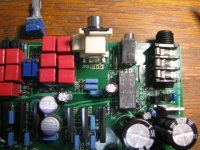
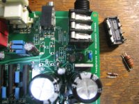
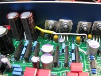
Below are some tests on the power transformer at the output of the CRC section. This is actually Alex's board under test here, after I converted it over to the new BOM parts. I asked Alex to mail it to me a few days ago since he already had his parts installed. I have a Hakko 808 here that can suck a golf ball through a garden hose. The parts that have been changed are the relay from the 48Vdc coil to 24Vdc, the D16 zener from 43V to 19V, and R70 from 3.01K to 1.47K
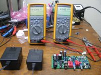
* The first photo shows the WAU16-2400 (16Vac 2.4A) on the left and the WAU16-1000 (16vac 1A) on the right. The blue wires I have soldered to the ODA board are just hooked to the outputs (JP8, JP9) and ground.
* The next photo shows the test setup with 33R load resistors on each power supply rail. The result is around 17Vdc / 33R = 510mA That comes from the maximum current output of the 6 op amps on each channel, 320mA, converted to rms which is 226mA (rms). Multiplied by 2 channels, plus about 60mA total quiescent current from all the chips gives (2)(226) + 60 = 512mA.
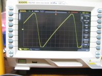
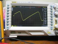
* The next one is a closeup of the scope in the above shot, which is using the smaller 16Vac 1A transformer. That is 500mV/div with the scope AC coupled, so we are looking at about 3.75V of ripple riding on top of the voltage.
* Next is the true RMS voltage on each rail, about +/-16.8Vdc. The true RMS value would be right in the middle of that fairly symmetrical ripple waveform above, so the bottom of the ripple would be this minus 1/2 of the ripple, or 16.8V - (3.75V/2) = 14.9Vdc. Already we have a problem. The output of the pre-regulators is set for 14.5Vdc now, to leave 2Vdc across the LDO chips producing the +/-12.5Vdc rails. The data sheet on the LM317/337 chips recommends a minimum of 3V drop to stay out of dropout, but experience recommends more like 5Vdc drop. But with these readings we would get only 14.9Vdc - 14.5Vdc - 0.4Vdc, which would put both pre-regulators into dropout. So the 16Vac 1A transformer is a no-go. Now keep in mind with a lighter load the transformer output voltage will rise several volts, but this is the worse-case testing under maximum load which is the limiting factor.
* Lets try again with the 16Vac 2.4A transformer in the next photo. This just shows the thicker supply lead from the beefier transformer.
* The scope shot and true RMS voltage readings are next, still with the 16Vac 2.4A transformer. Looking much better! The true RMS voltage is now all the way up to +/-19.8Vdc. Backing the scope down a range to get an accurate reading on the wave tips gives about 4.2V of ripple, or 2.1V for half. So now the voltage across the pre-regulators during the ripple minimums (at the absolute maximum load condition here) would be (19.8 - 2.1) - 14.5 = 3.1Vac = no dropout, as per the datasheet numbers. Now keep in mind this is full load continuous testing, which would never happen with real music coming out. Maximum load peaks like this are intermittant, giving me my preferred 5Vdc across the pre-regulators. So QED as they say in math class, 16Vac 2.4A is the transformer to use.
* The final two photos show the old parts after being extracted from Alex's board, then with the new parts installed. The only part that looks any different is R70, the relay circuit voltage set resistors, which is smaller.
Here is the verdict about which transformer is needed for the new +/-12.5Vdc "standard" power rails in the ODA - it is the larger 16Vac 2.4amp WAU16-2400 unit at Mouser. Their 20Vac 2A transformer could be used too, the WAU20-2000, but they have that priced at nearly double for some reason. The back panel would also get hotter with the 20Vac unit since that extra 4Vac would all be burned off by the pre-regulators.
BTW, I forgot to say in the previous post where that extra 0.5 volts in the +/-12.5Vdc power rails comes from. That really is not an attempt to just one-up NwAvGuy's +/-12.0Vdc power rails in his O2 headamp.
The inline SIP package of the NJM4556AL chips is rated at 100mW more, 800mW, vs. the DIP8 package (NJM4556A) at 700mW in the O2. So that extra 0.5 volts is using 20mW of the extra 100mW package power dissipation in each chip from quiescent (idle) current, leaving 80mW more for signal output per chip.Below are some tests on the power transformer at the output of the CRC section. This is actually Alex's board under test here, after I converted it over to the new BOM parts.
I asked Alex to mail it to me a few days ago since he already had his parts installed. I have a Hakko 808 here that can suck a golf ball through a garden hose. The parts that have been changed are the relay from the 48Vdc coil to 24Vdc, the D16 zener from 43V to 19V, and R70 from 3.01K to 1.47K* The first photo shows the WAU16-2400 (16Vac 2.4A) on the left and the WAU16-1000 (16vac 1A) on the right. The blue wires I have soldered to the ODA board are just hooked to the outputs (JP8, JP9) and ground.
* The next photo shows the test setup with 33R load resistors on each power supply rail. The result is around 17Vdc / 33R = 510mA That comes from the maximum current output of the 6 op amps on each channel, 320mA, converted to rms which is 226mA (rms). Multiplied by 2 channels, plus about 60mA total quiescent current from all the chips gives (2)(226) + 60 = 512mA.
* The next one is a closeup of the scope in the above shot, which is using the smaller 16Vac 1A transformer. That is 500mV/div with the scope AC coupled, so we are looking at about 3.75V of ripple riding on top of the voltage.
* Next is the true RMS voltage on each rail, about +/-16.8Vdc. The true RMS value would be right in the middle of that fairly symmetrical ripple waveform above, so the bottom of the ripple would be this minus 1/2 of the ripple, or 16.8V - (3.75V/2) = 14.9Vdc. Already we have a problem. The output of the pre-regulators is set for 14.5Vdc now, to leave 2Vdc across the LDO chips producing the +/-12.5Vdc rails. The data sheet on the LM317/337 chips recommends a minimum of 3V drop to stay out of dropout, but experience recommends more like 5Vdc drop. But with these readings we would get only 14.9Vdc - 14.5Vdc - 0.4Vdc, which would put both pre-regulators into dropout. So the 16Vac 1A transformer is a no-go. Now keep in mind with a lighter load the transformer output voltage will rise several volts, but this is the worse-case testing under maximum load which is the limiting factor.
* Lets try again with the 16Vac 2.4A transformer in the next photo. This just shows the thicker supply lead from the beefier transformer.
* The scope shot and true RMS voltage readings are next, still with the 16Vac 2.4A transformer. Looking much better! The true RMS voltage is now all the way up to +/-19.8Vdc. Backing the scope down a range to get an accurate reading on the wave tips gives about 4.2V of ripple, or 2.1V for half. So now the voltage across the pre-regulators during the ripple minimums (at the absolute maximum load condition here) would be (19.8 - 2.1) - 14.5 = 3.1Vac = no dropout, as per the datasheet numbers. Now keep in mind this is full load continuous testing, which would never happen with real music coming out. Maximum load peaks like this are intermittant, giving me my preferred 5Vdc across the pre-regulators. So QED as they say in math class, 16Vac 2.4A is the transformer to use.
* The final two photos show the old parts after being extracted from Alex's board, then with the new parts installed. The only part that looks any different is R70, the relay circuit voltage set resistors, which is smaller.
Attachments
-
 IMG_2654.JPG156.4 KB · Views: 51
 -
 IMG_2653.JPG151.9 KB · Views: 56
 -
 IMG_2652.JPG180.8 KB · Views: 181
 -
 IMG_2650.JPG161.8 KB · Views: 182
 -
 IMG_2648.JPG132 KB · Views: 183
 -
 IMG_2647.JPG214.6 KB · Views: 190
 -
 IMG_2645.JPG225.7 KB · Views: 191
 -
 IMG_2655.JPG155.9 KB · Views: 57
 -
 IMG_2643.JPG216.9 KB · Views: 65
 -
 IMG_2642.JPG197.7 KB · Views: 58
Last edited:
Alex's ODA works!!
I've just completed the rest of the power supply section on Alex's ODA, powered it up and... it works!! A big congratulations goes out to Alex on his build. Only one small mistake I see so far. The output levels are different on the 3rd gain switch setting so a gain resistor was put in the wrong place there. But out of this whole build that is trivial. GOOD JOB ALEX!
The back panel is just moderately warm around the voltage regulators (using the 16Vac 2.4A transformer here). That is just sitting here on the table, not even screwed onto the rest of the aluminum case which would heatsink it further. The Beyer DT770's I'm listening to it with right now are not much of a load though, as the photos below show. I would suggest waiting before you bolt any additional heatsinking on the back of your ODAs. You will probably find it not necessary, although I do think it looks kind of cool! Might want to do it just for looks. The vent hole is a very good idea and will get added to the rear panel CAD. Unfortunately that will also raise the panel cost. It looks like FPE charges $1 a hole or such.
I've also swapped the pot in Alex' build for the new 1K linear.
The photos are...
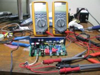
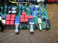
* I appologize for the blurry first one. This is the test setup for measuring the power supply voltages before the disconnects (JP18, JP19) have been connected to power the rest of the board. You can get the general idea. The 4 voltage regulators have been soldered on, mounted to a back panel, and the connection jumpers from the CRC section to the power section added (JP8 -> JP10, JP9 -JP11), Alex, I used some (yellow) sleeving over part of it to make the wires a little neater, as the next 3 photos show.
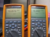
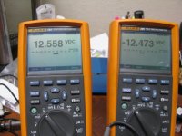
* The next one shows the power supply output voltages. We are shooting for +/-12.5Vdc and actually have +12.56 and -12.47. That is just fine. I've put the R33 and R36 positions in the power supply section specifically so folks can tweak that further just as much as they want. The references voltages built into the voltage regulators have a +/-tolerance, so there will always be a tiny amount of variance.
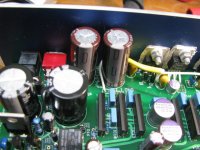
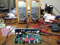
* Two green power LEDs in the next one.. it lives! I measured the resistance to ground on the two power supply rails after the disconnects first, before jumpering them, just to make sure nothing was shorted on the rails. Then I had DMMs on the rails when I first power up, after jumpering the disconnects, to make sure the power rails were OK.
* The next two photos show the typical setup for measuring the DC output offset, along with the results after adjusting the trimpots. 2uV (microvolts!) on one channel and 4uV on the other. I didn't take a picture of the intial power-on numbers before adjusting the trimpots, but one started out at about 140uV and the other at about 60uV. It took about 4 turns of the 25 turn trimpot to zero the first one out and 2 turns or so to zero out the other. Thermally they only drift about 15uV or so over time from the set point. Keep in mind NwAvGuy's O2 typically has 3000uV of DC output offset, so even if you adjusted nothing (if your DMM doesn't read below 1mA) you would still have 3000uV/140uV = 21 times lower DC output offset than the O2.
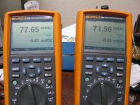
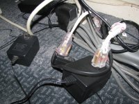
* The last two are Alex's ODA powering my Beyer DT770s. Not much a drive challenge though, just 77mV(rms). These are instantanous readings now, so they jump around all over the place with the music.
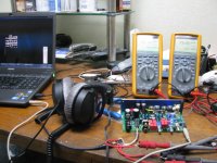
A fun first thing to try with any new ODA is pull out the input cable and flip the input select switch out so you get the grounded 3.5mm inputs. Then turn your volume control all the way up and your gain switch all the way up, then have a listen for any background noise. It is quiet out in space.. Don't forget to turn your control back down before listening to music.
I've just completed the rest of the power supply section on Alex's ODA, powered it up and... it works!! A big congratulations goes out to Alex on his build. Only one small mistake I see so far. The output levels are different on the 3rd gain switch setting so a gain resistor was put in the wrong place there. But out of this whole build that is trivial. GOOD JOB ALEX!
The back panel is just moderately warm around the voltage regulators (using the 16Vac 2.4A transformer here). That is just sitting here on the table, not even screwed onto the rest of the aluminum case which would heatsink it further. The Beyer DT770's I'm listening to it with right now are not much of a load though, as the photos below show. I would suggest waiting before you bolt any additional heatsinking on the back of your ODAs. You will probably find it not necessary, although I do think it looks kind of cool! Might want to do it just for looks. The vent hole is a very good idea and will get added to the rear panel CAD. Unfortunately that will also raise the panel cost. It looks like FPE charges $1 a hole or such.
I've also swapped the pot in Alex' build for the new 1K linear.
The photos are...
* I appologize for the blurry first one. This is the test setup for measuring the power supply voltages before the disconnects (JP18, JP19) have been connected to power the rest of the board. You can get the general idea. The 4 voltage regulators have been soldered on, mounted to a back panel, and the connection jumpers from the CRC section to the power section added (JP8 -> JP10, JP9 -JP11), Alex, I used some (yellow) sleeving over part of it to make the wires a little neater, as the next 3 photos show.
* The next one shows the power supply output voltages. We are shooting for +/-12.5Vdc and actually have +12.56 and -12.47. That is just fine. I've put the R33 and R36 positions in the power supply section specifically so folks can tweak that further just as much as they want. The references voltages built into the voltage regulators have a +/-tolerance, so there will always be a tiny amount of variance.
* Two green power LEDs in the next one.. it lives! I measured the resistance to ground on the two power supply rails after the disconnects first, before jumpering them, just to make sure nothing was shorted on the rails. Then I had DMMs on the rails when I first power up, after jumpering the disconnects, to make sure the power rails were OK.
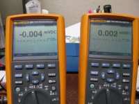
* The next two photos show the typical setup for measuring the DC output offset, along with the results after adjusting the trimpots. 2uV (microvolts!) on one channel and 4uV on the other. I didn't take a picture of the intial power-on numbers before adjusting the trimpots, but one started out at about 140uV and the other at about 60uV. It took about 4 turns of the 25 turn trimpot to zero the first one out and 2 turns or so to zero out the other. Thermally they only drift about 15uV or so over time from the set point. Keep in mind NwAvGuy's O2 typically has 3000uV of DC output offset, so even if you adjusted nothing (if your DMM doesn't read below 1mA) you would still have 3000uV/140uV = 21 times lower DC output offset than the O2.
* The last two are Alex's ODA powering my Beyer DT770s. Not much a drive challenge though, just 77mV(rms). These are instantanous readings now, so they jump around all over the place with the music.
A fun first thing to try with any new ODA is pull out the input cable and flip the input select switch out so you get the grounded 3.5mm inputs. Then turn your volume control all the way up and your gain switch all the way up, then have a listen for any background noise. It is quiet out in space..
Don't forget to turn your control back down before listening to music.Attachments
-
 IMG_2670.JPG168 KB · Views: 64
 -
 IMG_2669.JPG201.4 KB · Views: 62
 -
 IMG_2668.JPG159.2 KB · Views: 54
 -
 IMG_2667.JPG208.8 KB · Views: 62
 -
 IMG_2665.JPG203.9 KB · Views: 62
 -
 IMG_2661.JPG160.5 KB · Views: 54
 -
 IMG_2664.JPG187 KB · Views: 56
 -
 IMG_2663.JPG190.8 KB · Views: 56
 -
 IMG_2662.JPG181.6 KB · Views: 59
 -
 IMG_2660.JPG173.1 KB · Views: 61
Last edited:
Great, I am really glad the board works, at least no caps popped or smoked!!
I really enjoyed the build process and soldering, even the tiny SMD parts and IC's.
I did center the pots before I soldered them into the board...looks like it didn't take much to get them adjusted.
I am wondering about the gain resistor, haven't looked at the schematic for the values that I must have gotten mixed up but like you indicate its a easy fix. What I am wondering is if I indeed mixed these up where I put the correct gain resistor!!!
The heat-sinking looks like its probably not really needed, but it would look "cool" LOL
Looking forward to listening comparisons to the O2 across a wide variety of headphones in the neat future.
Thanks for all the help and assistance.
Alex
I am wondering about the gain resistor, haven't looked at the schematic for the values that I must have gotten mixed up but like you indicate its a easy fix. What I am wondering is if I indeed mixed these up where I put the correct gain resistor!!!
Well your build job is back to being 100% perfect.
I just did some measurements and the problem is a bad rotary gain switch. That one particular contact in the 3rd position isn't working. I'm sending a Mouser order out on Monday anyway so I'll get one and swap that out. The Hakko 808 rocks for getting multi-legged things like that rotary switch out without any damage to the part or PC board.- Home
- Amplifiers
- Headphone Systems
- A version of an O2 Desktop Amp (ODA)