$1700 Beyer A2 vs. the $330 ODA
I just spotted something new and had a bit of a chuckle that I had to share. Beyerdynaic has released a $1700 desktop headphone amp called the A2:
http://europe.beyerdynamic.com/shop/media/datenblaetter/DAT_A2_EN_.pdf
Other than the fancy case, which I admit is impressive, in reading through the specs here is what I noticed vs. the ODA. I'm saying $330 for the ODA which is $200 parts, $25 transformer, $25 case, and $70 or so for the drilled and labeled front and rear panels from cam-expert.com or front panel express.
* The A2 has two 1/4" output jacks in parallel on the front panel. The ODA has one 3.5mm out and one 1/4" out on the front panel, but you could use a 1/4" Y cable to put two 1/4" in parallel.
* It has two RCA jack inputs on the rear, switch selectable. The ODA has an RCA input on the rear plus a 3.5mm input on the front, switch selectable.
* It has the "unique feature" of optionally matching the headamp output to the phones, ie, O ohm out or 100 ohms out. Well... that is what R88 and R89 are for. "U pick it" output impedance, from 0.083R with them jumpered to anything you want to solder in there, including 100 ohms, or that optional 6 position external selection switch.
* The A2 has a remote control, backlit standby button and nice aluminum headphone stand. Got me there.
* The A2 has selectable gain, 0dB, 4dB, 6dB. The ODA has all that (the gain resistors can be set for anything) plus has 1 additional gain setting on the 4 position rotatary switch. Plus the default is 1/2x attentuation on the low end for "hot" sources that just need the current buffer.
* One of the A2's RCA inputs is looped through (to an RCA output) for line level pass through. Check! You can wire the front panel pre-amp RCA out jack up that way in the ODA. Plus you can wire that pre-amp MUSES8820 chip in for current buffering and/or voltage gain.
* Mute feature on the remote control in the A2.. Hmm... lemme think about that. The ODA's headphone relay coil could likely be wired through an external switch to produce a headphone mute function. The ODA even has the reverse coil voltage suppression parts that would prevent pitting the switch contacts over time.
* For the A2, "the components inside are illuminated by a warm orange glow that can be seen through the top glass". Well heck, even have that one covered! The ODA's innards are illuminated by a nice cool blue glow from LED1 and LED2, but not visible by anyone though unless someone wants to cut a hole in the top. By the way, I need to add this to the build instructions, don't substitute other LED colors there. Just like in the O2 those leds are used as voltage references. Different colors have different forward voltages.
* The A2 is discrete while the ODA is all IC. But the IC's are similar to NwAvGuy's selections, or "datasheet better" in the case of the LME4990 so all his arguments vs. discrete apply...
* A2: "due to an microprocessor controlled [headphone] relay an unpleasant crackling noise is eliminated on on/off". Check! ODA's headphone relay does the same thing using an analog circuit.
* The A2 does about 170mW per channel. The ODA can do about 5x that even with the attentuation resistors installed.
I'm not trying to diss Beyerdynamic here, I have a pair of Beyer phones myself and love them. Beyer rocks. The price difference just sort of jolted me!
All of this reminds me that I've forgotten to update the "O2 headphone amp vs. ODA" chart I posted in last year's version. I've added another column for "vs. O2 booster board" now too. This is also posted out at the project google drive link. now
I just spotted something new and had a bit of a chuckle that I had to share. Beyerdynaic has released a $1700 desktop headphone amp called the A2:
http://europe.beyerdynamic.com/shop/media/datenblaetter/DAT_A2_EN_.pdf
Other than the fancy case, which I admit is impressive, in reading through the specs here is what I noticed vs. the ODA. I'm saying $330 for the ODA which is $200 parts, $25 transformer, $25 case, and $70 or so for the drilled and labeled front and rear panels from cam-expert.com or front panel express.
* The A2 has two 1/4" output jacks in parallel on the front panel. The ODA has one 3.5mm out and one 1/4" out on the front panel, but you could use a 1/4" Y cable to put two 1/4" in parallel.
* It has two RCA jack inputs on the rear, switch selectable. The ODA has an RCA input on the rear plus a 3.5mm input on the front, switch selectable.
* It has the "unique feature" of optionally matching the headamp output to the phones, ie, O ohm out or 100 ohms out. Well... that is what R88 and R89 are for.
"U pick it" output impedance, from 0.083R with them jumpered to anything you want to solder in there, including 100 ohms, or that optional 6 position external selection switch.* The A2 has a remote control, backlit standby button and nice aluminum headphone stand. Got me there.
* The A2 has selectable gain, 0dB, 4dB, 6dB. The ODA has all that (the gain resistors can be set for anything) plus has 1 additional gain setting on the 4 position rotatary switch. Plus the default is 1/2x attentuation on the low end for "hot" sources that just need the current buffer.
* One of the A2's RCA inputs is looped through (to an RCA output) for line level pass through. Check! You can wire the front panel pre-amp RCA out jack up that way in the ODA. Plus you can wire that pre-amp MUSES8820 chip in for current buffering and/or voltage gain.
* Mute feature on the remote control in the A2.. Hmm... lemme think about that. The ODA's headphone relay coil could likely be wired through an external switch to produce a headphone mute function. The ODA even has the reverse coil voltage suppression parts that would prevent pitting the switch contacts over time.
* For the A2, "the components inside are illuminated by a warm orange glow that can be seen through the top glass". Well heck, even have that one covered!
The ODA's innards are illuminated by a nice cool blue glow from LED1 and LED2, but not visible by anyone though unless someone wants to cut a hole in the top. By the way, I need to add this to the build instructions, don't substitute other LED colors there. Just like in the O2 those leds are used as voltage references. Different colors have different forward voltages.* The A2 is discrete while the ODA is all IC. But the IC's are similar to NwAvGuy's selections, or "datasheet better" in the case of the LME4990 so all his arguments vs. discrete apply...
* A2: "due to an microprocessor controlled [headphone] relay an unpleasant crackling noise is eliminated on on/off". Check! ODA's headphone relay does the same thing using an analog circuit.
* The A2 does about 170mW per channel. The ODA can do about 5x that even with the attentuation resistors installed.
I'm not trying to diss Beyerdynamic here, I have a pair of Beyer phones myself and love them. Beyer rocks. The price difference just sort of jolted me!
All of this reminds me that I've forgotten to update the "O2 headphone amp vs. ODA" chart I posted in last year's version. I've added another column for "vs. O2 booster board" now too. This is also posted out at the project google drive link. now
Attachments
Last edited:
Ah....a fool and his money are soon parted....but it sure looks pretty!!
What can I say....I like "stuff" but realistically sonically it wont perform any better than a O2 or and ODA in my humble opinion..and these are fightin words!!
Oppo also is working on a headphone amp not yet priced but I am sure it will be in the $1K area.
Why would any real headphone person want anything less expensive!!
LOL
Oh well back to soldering!!
Got all the WIMA caps in, thur will be a good day when I get most of the other stuff needed.
Once we get it running in the "nude" I will start on drilling holes with my drill press.
Need to find away to label at least the front panel ...hmmm thinking..
Alex
Note: One thing with DIY is you can change stuff etc....experiment etc...to some this is really scary and not in their realm or their capability, many of us are appliance operators who just want stuff to work and work well. Its not to meant to be a slam against anyone...I still buy stuff and appreciate a good design etc..but with DIY you can have world class performance for a whole lot less money IMO. It may not look as pretty as commercial enclosures but it sure performs as well and some cases even better! Being retired and on a fixed income I find it harder to justify the more costly commercial stuff out there!
Last edited:
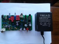
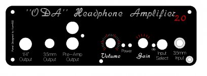
Panels and parts arrived
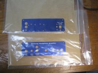
The set of front and back panels I ordered from cam-expert.com arrived today. The good news is the machining job looks excellent, and so does the fonts that I picked for the text. That bad news is that their color of blue anodization is more of a navy blue, while the B4-080 case (and the panel from Front Panel Express) are a lighter semi-metallic color of blue. Pictures attached below. In the last picture that is the FPE rear panel atttached to the box.
So... it would probably be worth the extra 20% cost to get the panels from FPE to get a closer color match.
The other news is that a package from Mouser arrived. I'll get the 5.49K resistors for that DC null circuit change and the 1N4004 (or 1N4002 or 4006, any of these will work) diodes with the skinnier leads to fit the D3-D6 and D15 holes in the mail today.
Attachments
Last edited:
Can you sent the panels that come with the B4-080 to these companies and have them just engraved for a lesser fee? Then the color would match?
Took yesterday off to real world things!! Start again today as soon as care packages arrive and I hope the AC transformer...
Re-checking all the diodes, caps, shorts etc..
Alex
Took yesterday off to real world things!! Start again today as soon as care packages arrive and I hope the AC transformer...
Re-checking all the diodes, caps, shorts etc..
Alex
Last edited:
Can you sent the panels that come with the B4-080 to these companies and have them just engraved for a lesser fee? Then the color would match?
Front Panel Express will allow sending them blank panels, but they only knock about $3 off the price. That gets eaten up by postage in sending them the panel so it doesn't save any money. But the color would be an exact match and the edges would be colored. If they mill the panel themselves the edges wind up bare aluminum.
I'll check with cam-expert to see if they allow sending in blank panels.
In other news I've starting building up another board and I'm taking high resolution pictures this time, as promised. They are at the project Google Drive link under photos->high resolution. Should be able to zoom those up a great deal to see detail.
I've also updated the build instructions at the Google Drive link. I've added a summary of what the ODA does at the top now, similar to what I have in the O2 booster board instructions.
Well the care package arrived from agdr with the BOM resistor changes and the 24VAC xfmr arrived from Mouser with my T0-220 mount kits.
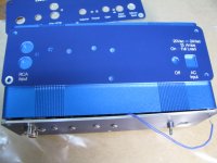
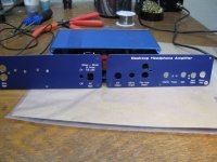
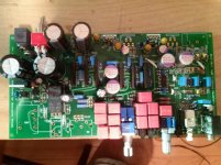
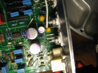
I applied power to the first step power area and checked the voltages and got +/- 35.8 volts and 47.7 volts dc for the relay and the relay clicked after bout 5 seconds...so its on to the final stretch!!
Heres a pix so far, still lackin ga few items...but really close!
Alex
(smiling)..
Still waiting on the enclosure to arrive
Attachments
Alex - good work on your build! Those voltage measurements are right on the mark.
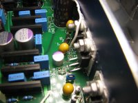
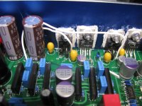
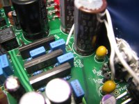
I've just realized that I never photo-posted what you need for the next step, connecting the JP8 bottom hole to JP10 and the JP9 right hand hole to JP11.
I have things set up this way just so I don't have to put traces with the power supply sawtooth wave right on top of the clean power traces going out to the amp chips. It is essentially a by-product of this "sideways" layout with the power parts all spread out along the back panel for heatsinking. Usually with power supplies the traces just flow from input at one side of the board to output at the other.
* The first 3 photos show a 22 gauge wire going from the bottom hole of JP8 to JP10. Route the wire behind C12, between C12 and the back panel. The big thing to watch out for here is that you get JP10, not JP16 which is right next to it. JP10 is the one in front of IC3. JP16 is just a test point on the output of the positive pre-regulator, which it goes into the final positive LDO regulator. Nothing connects to it.
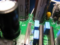
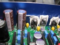
* The next 3 photos show a 22 gauge wire going from the righthand hole of JP9 to JP11. Again the thing to watch out for here is that you get JP11, not JP17. JP11 is the one in front of IC4 (take a look at the Part ID diagram if the text labels are covered up by the parts). JP17 is just a test point again on the output of the negative pre-regulator, which it goes into the final negative LDO regulator.
In some other project news, cam-expert.com did confirm today that they can use the blank panels mailed to them. They knock about $3 off the cost. They quoted $36.50 for the front panel and $26.30 for the rear, plus shipping, for drilling and text engraving customer-supplied panels.
And as for the pre-amp chip, I chatted with Mouser today and my speculation back in post #334 was right on the mark. It may be a while before that MUSES8820E chip is available again from them. Best to just go with the LME49720 that is in the BOM.
I have also posted an updated set of build instructions at the google drive link that includes Alex's feedback here on several items.
I've just realized that I never photo-posted what you need for the next step, connecting the JP8 bottom hole to JP10 and the JP9 right hand hole to JP11.
I have things set up this way just so I don't have to put traces with the power supply sawtooth wave right on top of the clean power traces going out to the amp chips. It is essentially a by-product of this "sideways" layout with the power parts all spread out along the back panel for heatsinking. Usually with power supplies the traces just flow from input at one side of the board to output at the other.
* The first 3 photos show a 22 gauge wire going from the bottom hole of JP8 to JP10. Route the wire behind C12, between C12 and the back panel. The big thing to watch out for here is that you get JP10, not JP16 which is right next to it. JP10 is the one in front of IC3. JP16 is just a test point on the output of the positive pre-regulator, which it goes into the final positive LDO regulator. Nothing connects to it.
* The next 3 photos show a 22 gauge wire going from the righthand hole of JP9 to JP11. Again the thing to watch out for here is that you get JP11, not JP17. JP11 is the one in front of IC4 (take a look at the Part ID diagram if the text labels are covered up by the parts). JP17 is just a test point again on the output of the negative pre-regulator, which it goes into the final negative LDO regulator.
In some other project news, cam-expert.com did confirm today that they can use the blank panels mailed to them. They knock about $3 off the cost. They quoted $36.50 for the front panel and $26.30 for the rear, plus shipping, for drilling and text engraving customer-supplied panels.
And as for the pre-amp chip, I chatted with Mouser today and my speculation back in post #334 was right on the mark. It may be a while before that MUSES8820E chip is available again from them. Best to just go with the LME49720 that is in the BOM.
I have also posted an updated set of build instructions at the google drive link that includes Alex's feedback here on several items.
Attachments
Last edited:
It looks like the Mouser part listed for R28 in the BOM is out of stock and the estimated lead-time is a couple months.
The suggested R28 is a bit unusual in that it's a 1/8W resistor in a 1206 package and they're usually 1/4W. It looks like Mouser has both some 1/8W 0805 parts (e.g. Vishay TNPW080540K2BEEA or Panasonic ERA-6AEB4022V) which are a bit smaller but look like they should still work, or some 1/4W 1206 parts (e.g. Vishay TNPW120640K2BEEA) - I assume any of these should be fine? Or maybe you could even safely choose a slightly different resistance if it's just an LED resistor?
The suggested R28 is a bit unusual in that it's a 1/8W resistor in a 1206 package and they're usually 1/4W. It looks like Mouser has both some 1/8W 0805 parts (e.g. Vishay TNPW080540K2BEEA or Panasonic ERA-6AEB4022V) which are a bit smaller but look like they should still work, or some 1/4W 1206 parts (e.g. Vishay TNPW120640K2BEEA) - I assume any of these should be fine? Or maybe you could even safely choose a slightly different resistance if it's just an LED resistor?
Last edited:
It looks like the Mouser part listed for R28 in the BOM is out of stock and the estimated lead-time is a couple months.
The suggested R28 is a bit unusual in that it's a 1/8W resistor in a 1206 package and they're usually 1/4W. It looks like Mouser has both some 1/8W 0805 parts (e.g. Vishay TNPW080540K2BEEA or Panasonic ERA-6AEB4022V) which are a bit smaller but look like they should still work, or some 1/4W 1206 parts (e.g. Vishay TNPW120640K2BEEA) - I assume any of these should be fine? Or maybe you could even safely choose a slightly different resistance if it's just an LED resistor?
Hi, thanks for the out-of-stock update on that one!
Using the 1/4W 71-TNPW120640K2BEEA part is OK. There was no elecgtrical need for 1/8W there - the dissipation is about 25mW - the 1/8W KOA parts are usually just cheaper at $0.50 vs. usually $0.85 for the 1/4W parts. I use those when I can. But in this case that 71-TNPW120640K2BEEA is priced at $0.55, nearly the same, and is a part that Digikey would also have (they don't stock KOA). So I'm going to switch the part in the BOM to the 71-TNPW120640K2BEEA and move that KOA part to the notes as an alternate, to solve the out of stock problem. In fact, it looks like I had the Vishay part in there at one time. I have 1/4W and Vishay listed. I must have switched it over to the 1/8W KOA part at some point for cost savings and didn't update the rest of the line. Good find!!
Also - important - if you haven't placed your Mouser order yet I would suggest waiting a few days. I'm looking at possibly changing a resistor value. More info in another post...
Last edited:
Is it possible to put the jumper wires underneath the board??
To make it a cleaner install?
Use shielded cable?
Alex
One idea here is to use some "spaghetti" tubing to slip over the two wires in the mid-section. I have some clear silicon stuff that would fit those just perfectly. May have some white too. It is perfectly OK if those two wires are right next to each other (in the tubing).
I do have some mini-coax, but after some tests it didn't make any difference electrically and stripping the stuff will make a person go cross-eyed.
Then there is the problem of the shield accidently touching surrounding parts, expecially on the voltage regulator end. But a way around that would be to leave the shield a bit long, bend it back over the cable, then slip some heat shrink tubing around it. Alex - or anyone else - if you would like to mess around with the mini-coax just let me know. I'll drop some in an envelope for you. They way it works is the center lead goes in the holes indicated in the photo build by C12, and the shield goes to the other hole, which is ground. Then on the other end of the cable (the voltage regulator end) it is just the center lead that goes in the hole. In other words, the shield is grounded at just one end.
So for example, with JP8, the center lead of the mini-coax would go to the bottom hole and the shield to the other hole. Then on the other end of the mini-coax you use just the center lead of the mini-coax in JP10, wiht the shield cut away. But you have to make sure any exposed edges of the shield on that end won't touch anything surrounding - hence that heat shrink tubing trick above.
Last edited:
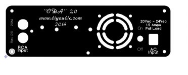
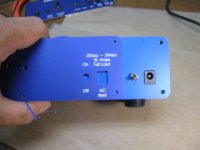
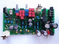
And heres the back panel for the ODA
I really like how those panels look!
A (low noise) fan is good addition.I've heard a lot from some corners about how fans are bad because they help build up electrostatic charge on the surface of components due to airflow and that the rotating magnets in fan bearings interfere with sound quality, but in the "objective" spirit I've never seen any quantitative evidence for that being true.
I'm a fan of Noctua fans in particular and have used them in various projects, usually with a temperatures sensor, since they make some small ones (e.g. 40mm and under) which only put out ~10db which is pretty much silent. They'd squeeze inside a B4-080BL enclosure, but probably not once you got the board in there and regulators heatsunk to the panel. You'd also need to make sure there was an intake somewhere near the front.
I'm a fan of Noctua fans in particular and have used them in various projects, usually with a temperatures sensor, since they make some small ones (e.g. 40mm and under) which only put out ~10db which is pretty much silent. They'd squeeze inside a B4-080BL enclosure, but probably not once you got the board in there and regulators heatsunk to the panel. You'd also need to make sure there was an intake somewhere near the front.
- Home
- Amplifiers
- Headphone Systems
- A version of an O2 Desktop Amp (ODA)