Okay, some quotes:
U Case 1 – U1S – 204mm x 100mm x 44mm (Silver Extrusions, Pre Ano, Top, Bottom, Front & Rear)
1 off £65.93 Shipping £18.00
10 off £ 14.79 each Shipping £42.00
U Case 1 – U1S – 204mm x 150mm x 44mm (Silver Extrusions, Pre Ano, Top, Bottom, Front & Rear)
1 off £69.90 Shipping £18.00
10 off £ 18.36 each Shipping £42.00
This is for the cheapest case, I've asked for quotes or anodising silver or black (which'll cost a bit more, I hope not much more) and for 5 or 10 units since only 1 is way too expensive.
Is anodising the case necessary?
From past orders, how many cases do you reckon will be needed?
They also mill and punch both box and end plates, I've sent links to your google folder for the current ODA, hopefully that should give them rough ideas of how much drilling we want done for a quote.
I'd hope it comes under $50 for the bigger case to be fully anodised and shipped to the US per unit with end plates, but it may end up being ~$65. We'll have to see I suppose - but it would give a lot more board space.
@Turbon: Thanks! If there's enough interest in the bigger case for it to be affordable agdr can use the extra space for his filters.
@agdr: they've replied with this:
"Is there a way that the drawing can be converted into a DXF file or something which is more commonly used as we cannot open the drawing
Thus cannot see what I am quoting for. ( We use coral draw, or solid works )"
Would you have a quick conversion?
Also, what is the cost of the current front/back panel combo? I think if we get case+panels from LincolnBinns we may end up getting a pretty good deal for the three compared to the current BOM.
Is anodising the case necessary?
From past orders, how many cases do you reckon will be needed?
Anodization is not necessary. In fact it is a problem that has to be delt with. The annodization is an insulator, so that is why I've had to countersink a few holes in the panels, to slice though the annodization and get a good electrical contact.
The current "next board" list is up to about 20. For a larger board and case that is more expensive I would guess maybe 5 - 10 people might step up. That may not be enough to get much of a quantity discount.
@agdr: they've replied with this:
"Is there a way that the drawing can be converted into a DXF file or something which is more commonly used as we cannot open the drawing
Thus cannot see what I am quoting for. ( We use coral draw, or solid works )"
Would you have a quick conversion?
I don't have a conversion program, but the program that reads those .fpe files is a free download at Front Panel Express, the "Front Panel Designer" here:
Front Panel Express:*Customize Your Front Panel and Enclosure Design
if they would be willing to load that on a PC. Also I have all the measurements in a Excel spreadsheet file out at the project Google Drive link (in the first post of this thread). Go to 80x160mm -> 3_19_2014 V2.0 -> panels folder, then the .xlsx in there.
There are pictures of the panels and the box out at the "photos" folder. Maybe they could even come up with a rough estimate just based on the pictures, in terms of number of holes. The panels are 170mm wide x 53mm tall x 2mm thick. Anodization is not necessary.
Also, what is the cost of the current front/back panel combo? I think if we get case+panels from LincolnBinns we may end up getting a pretty good deal for the three compared to the current BOM.
Now that would be interesting! A place that could do the panels as well as the cases. Right now at Front Panel Express both panels combined are around $100 USD, or at least they will be after I add a few more vent holes in the back panel. Right now without the vent holes the total for both panels is around $85 USD.
Well... I'm pondering some ideas for a larger PCB.
 It would be a V3.0 at some point in the future. But on the new V2.1 going out in a week or two I will see if I can add holes attached to those LT regulator set resistors. That would make it easier to wire those across to an external voltage setting switch.
Some ideas for a V3.0 -
* Add the inductors back in the CRC section to go back to a CLC. The coils I had in originally were not shielded and coupled into a nearby ground trace. Sheilded coils are too large for the current board. I could go back to sheilded 100uH inductors. The whole goal of the CRC or CLC filter is to block incomming RF / EMI conducted from the power line and/or picked up by the power lead. I always try to design for the worst case. Instead of assuming clean power coming in I assume a person lives next to a metal plating shop on one side and a welding shop on the other, both of which attach to the same pole transformer as the house, then a satellite dish uplink farm across the street. I've lived in Los Angeles for awhile, lol.
I've actually seen that kind of situation. There are some amazingly electrically noisy commercial operations butted up next to residential areas, on the same power grids and within EMI radiation distance.* Something I was thinking about doing originally but didn't have the board space was add yet another LDO regulator, one of the TI ultra-low noise recent units that have both rails at about 500mA max, to power just the gain stage chips. In addition to even further reduced power rail noise this would dramatically isolate the gain stage power from the output stage class AB transition current spikes (and resultant voltage variations on the power rails).
* I could potentially add pads for a voltage select switch again that could be optionally installed, along with resistors, or left out for fixed voltage.
* There would probably be room to switch the IC5 clipping detect chip (14 pin TLO64) back to through-hole with a socket rather than the 14 pin SOIC. That is the hardest chip to solder on the whole board.
* And maybe room for the crossfeed!
Last edited:
More V2.1 additions
Here are some more additions and changes for V2.1. I think it is getting close to being finalized!
* Added a fuse just above the power input jack. A picofuse with wire leads, on end to fit in the space.
* Added a bidirectional transorb diode across the AC power input. This will help snuff out fast moving power line transients. It should respond faster than the MOVs in a typical surge supressor power strip. I've seen at least one situation over the years where a loose 100 amp feed wire to a power panel was causing fast transients throughout an office building that surge strips wouldn't touch. Gas discharge tubes nailed them though until the power panel problem was found and fixed. The transorb response time should be somewhere between a MOV and a gas discharge tube.
* Changed the two 200K through-hole resistors in the relay circuit section to surface mount and changed the 4.7uF relay timing capacitor to surface mount. I've placed a few parts underneath the 1/4" jack. Then moved all the parts up toward the 1/4"jack a bit. All of this allows the IC11 regulator to move up a bit. This provides more room now that IC11 has a heat sink. It may even provide enough room for the next larger size heatsink with longer fins. I'm going to try to place PC mounting holes so the version of that heat sink with PC mount pins can be used. The change makes good use of the unused board space under the 1/4" jack.
* I discovered that the C51 and C52 decoupling capacitors were returning to a different ground star segment than the rest of the output parts. This is fixed and a new ground star segment is run to C38 and C39. I've made some layout changes around those capacitors to make them more specifically for the gain stage. For folks with existing V2.0 boards none of this should make any audible difference. Those C51 and C52 caps are just decoupling to supress any oscillations. I'm just cleaning the layout up a bit here is all, and it may eventually make a difference with very sensitive dScope or AP analyzer tests.
* I'm getting a quote on having the V2.1 boards done in 2oz copper rather than 1oz. Related to that I've decreased the size of the traces that go by the bottom right pin of S2 to 0.3mm from 0.4. Those traces are the tightest squeeze on the board. 2oz copper needs more spacing between traces for the etch to work, so I wanted to open that trace to hole spacing up a bit. The current through those traces are extremely small so it won't make any electrical difference.
Attachments
Last edited:
Ok, order is ready to be sent to Mouser. I just want to check that the bom on the Google drive is complete with the latest changes except for the c11/12 change. Anything else? Yes, I left out the case and knobs.
Yep, the BOM is all up to date!
Last edited:
Yep, the BOM is all up to date!
Thanks, I'll send the order today.
Regards
Does the annodisation affect the case's ability to act as a heatsink? And what are the reasons for the case to be electrically conductive - iirc it is that the case is being used as a ground, but are there any other reasons? If that is the only reason, thanks to the U-Case 1 being split into parts it could be possible for just the bottom panel not to be anodised - something which from what I understand helps improve form, but with this may not be at the cost of function.Anodization is not necessary. In fact it is a problem that has to be delt with. The annodization is an insulator, so that is why I've had to countersink a few holes in the panels, to slice though the annodization and get a good electrical contact.
They do know what they are doing, so as long as I tell them everything you need the case to be (so far: big enough, heatsink, will tell them about the ground) they'll know what will and won't work.
The current "next board" list is up to about 20. For a larger board and case that is more expensive I would guess maybe 5 - 10 people might step up. That may not be enough to get much of a quantity discount.
Now that would be interesting! A place that could do the panels as well as the cases. Right now at Front Panel Express both panels combined are around $100 USD, or at least they will be after I add a few more vent holes in the back panel. Right now without the vent holes the total for both panels is around $85 USD.
I'll see about getting rough quotes for the panels and cases, I think there's a good chance it could come in under/around the current BOM price-wise. At the very least the 200mmx100mm case shouldn't be significantly more expensive, if we can get enough interest on our end. If I get quotes for 5+ or 10+ cases are you able to contact the people who signed up to see if they would be interested?
Thanks, I'll point LincolnBinns to both of these I've already asked them to do the last bit, but I missed the xlsx.I don't have a conversion program, but the program that reads those .fpe files is a free download at Front Panel Express, the "Front Panel Designer" here:
Front Panel Express:*Customize Your Front Panel and Enclosure Design
if they would be willing to load that on a PC. Also I have all the measurements in a Excel spreadsheet file out at the project Google Drive link (in the first post of this thread). Go to 80x160mm -> 3_19_2014 V2.0 -> panels folder, then the .xlsx in there.
There are pictures of the panels and the box out at the "photos" folder. Maybe they could even come up with a rough estimate just based on the pictures, in terms of number of holes. The panels are 170mm wide x 53mm tall x 2mm thick. Anodization is not necessary.
Well... I'm pondering some ideas for a larger PCB.
* I could potentially add pads for a voltage select switch again that could be optionally installed, along with resistors, or left out for fixed voltage.
* And maybe room for the crossfeed!
Panel-wise, I've asked if they could quote us for the most complicated design (in bulk) then produce some panels without certain holes and their respective markings if we provide the drawings. That should work well for both of us - they get paid for some holes they don't cut, we get the bulk discount and customised panels depending on what we want. And it'll be easier from a PCB designing perspective too if the layout is standard.
I'd say get the core circuit really good and measured really good before moving onto the crossfeed and bass boost, but that's just me. After all, if there's room left to play about with why not?
Hey
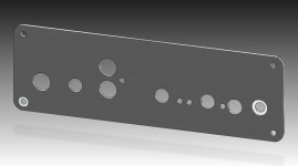
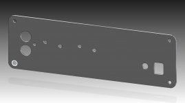
Here are some files case maker can use. In zip file there are stp files that can be opened in Solid works.
Please can someone check if all measurements are ok. I attached PDF files with technical drawings.
Cheers
Here are some files case maker can use. In zip file there are stp files that can be opened in Solid works.
Please can someone check if all measurements are ok. I attached PDF files with technical drawings.
Cheers
Attachments
Hey
Here are some files case maker can use. In zip file there are stp files that can be opened in Solid works.
Please can someone check if all measurements are ok. I attached PDF files with technical drawings.
Cheers
Nice, I'll leave the checking to someone who are into mechanics
Regards
Hey
Here are some files case maker can use. In zip file there are stp files that can be opened in Solid works.
Please can someone check if all measurements are ok. I attached PDF files with technical drawings.
Cheers
Thanks! I've sent them your files and the "official" xlsx so that should be fine. They were able to open the included files anyway.
If you want I can add few holes for cooling but you would have to specify where to put them since I don't have my own ODA.
@agdr: This'd increase LincolnBinns price if necessary and I didn't mention it to them, please let me now if so.
Also, they'd like to know what font size (and font?) you used.
A neat feature on an amp I say today was to auto-mute when the headphones were removed, and only unmute after the headphones were plugged back in and then the volume turned down to 0.
A neat feature on an amp I say today was to auto-mute when the headphones were removed, and only unmute after the headphones were plugged back in and then the volume turned down to 0.
That is slick! I can't think of a way to do that in analog though, offhand. It would probably require a microcontroller, some software, and a digitally controlled volume chip. A nice feature though!
Well I've realized today there would be a big show-stopper in using a larger PC board. The $500 Eagle license I have is only good for 100 x 160 maximum area. I had forgotten about that. To go larger it would be their "professional" license for another $550, not worth the investment for hobby stuff unfortunately.
But the LincolnBinns case that was the exact size of the B4-080 Box Enclosures case would still be handy for anyone in Europe, especially if they have the ability to fabricate the panels too and roll it together for one price. Up until now the only source of cases in Europe has been Farnell.
You've asked some good questions but unfortunately I'll have to answer them tomorrow. I'm having to catch a plane early tomorrow morning.
Here are some files case maker can use. In zip file there are stp files that can be opened in Solid works.
Thank you!! That gives the files in another format that is more universal.
ODA V2.1 is now out for PC board fabrication!
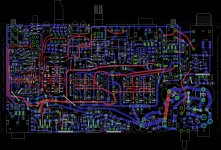
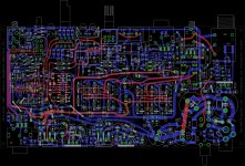
I was able to get the final bits of revision done on V2.1 last night. I sent it out for fabrication today. The layout below is what went out.
I did get a quote back on 2oz copper and it was nearly double the cost. Not worth it since it really wouldn't make any significant electrical difference. The fabrication should take around 5 business days, then around 7 days in the mail to get back to me, then building one up and testing it!
Here are the last changes to the board:
* I changed the holes near the rear RCA jack to Molex spacing, as dace suggested.
* I've added an additional set of Schottky rail clamp diodes before the power disconnects. When I added those disconnects it left the rail clamp diodes on the other side. Those diodes are important in dual rail power supplies to make sure the rails maintain the proper polarity during the instant when starting up. Usually one voltage regulator (positive or negative) will start up and instant of time faster than the other, leaving the opposing rail with the wrong polarity voltage for an instant (via rail to rail parts). The rail clamp diodes prevent that. The adjust resistors for the negative LDO got moved to the unused space under the rear RCA jack to make one diode fit.
* I was able to add a hole for a heatsink mounting pin in front of IC11. If my measurements work out there we will be able to use the version of that heatsink with one PC mounting pin.
* I wasn't able to fit in holes to attach wires to the LDO adjust pins for an external voltage select switch. I see thought that those wires can just be soldered onto pins 2 and 4 of the LDO regulator chips on the top (or bottom) of the board.
* Numerous other small layout tweaks.
Attachments
That is slick! I can't think of a way to do that in analog though, offhand. It would probably require a microcontroller, some software, and a digitally controlled volume chip. A nice feature though!
Perhaps my very basic electrical knowledge could help here: transistors. Let the very final component were a transistor, and we put the signal through that. If the transistor is the type which switches "on" when the gate recieves a pulse and "off" when the input turns off, you could feed the transistor's input and output into a NAND logic gate and that output into the transistor's gate.
If I haven't messed up the electronics this should work in theory, but it'd need someone who knows what they're doing to actually make it work. An advantage is that each output would be controlled separately - unplugging the 3.5mm jack wouldn't affect the 6.3mm one, and vice versa, though to reuse the jack you'd have to zero the volume.
Disadvantage is more noise, more soldering, more board space, etc.
Well I've realized today there would be a big show-stopper in using a larger PC board. The $500 Eagle license I have is only good for 100 x 160 maximum area. I had forgotten about that. To go larger it would be their "professional" license for another $550, not worth the investment for hobby stuff unfortunately.
Well that's a bummer. I've sent them an email to ask if there's any possibility of just getting more routing area on this board for a lower price - the Professional version has 180x more board space than we'd ever need and 4x the current number of layers we're using. I don't hold much hope there though.
Maybe if they were able to activate the tracking feature (like in the Hobbyist package) and you signed an agreement to limit yourself to a certain number of layers/board size they may let you use the Professional, or they can alter the program parameters to give you more space. Again there's little hope here.
Final option could be to make everything 1/2 the size and ask Seeed to stretch the PCB by a factor of 2. Or just stick with what you have already.
But the LincolnBinns case that was the exact size of the B4-080 Box Enclosures case would still be handy for anyone in Europe, especially if they have the ability to fabricate the panels too and roll it together for one price. Up until now the only source of cases in Europe has been Farnell.
True, but it'd have to be cut to 100mm so may not really be an option. I know HeadnHifi sell kits for a good price, and they've bulk ordered a lot of stock so both the kits and cases separately are already available at good prices.
You've asked some good questions but unfortunately I'll have to answer them tomorrow. I'm having to catch a plane early tomorrow morning.
Have a good flight!
Does the annodisation affect the case's ability to act as a heatsink? And what are the reasons for the case to be electrically conductive - iirc it is that the case is being used as a ground, but are there any other reasons?
The electrically conductive case is all for EMI (noise) sheilding. The anodization probably does have an effect on heat transfer, but I haven't looked into it. For the ODA just the rear panel alone is enough to dissipate the heat. Any heat transferred to the rest of the case is a bonus.
There have been several people who have boxed up NwAvGuy's O2 headphone amp in non-conductive cases. Plastic, wood, even bamboo. In general I haven't read any problems with noise. The same would probably be true with the ODA. The metal case is just sort of worse-case protection for RF noisy environments.
@agdr: This'd increase LincolnBinns price if necessary and I didn't mention it to them, please let me now if so.
Also, they'd like to know what font size (and font?) you used.
If you want I can add few holes for cooling but you would have to specify where to put them since I don't have my own ODA.
I still haven't added vent holes to the rear panel. Lets see if I can get time this weekend to do it.
On the one I sent out for dScope testing I just drilled one hole above each pre-regulator and one above the switch/power jack. I really like the slots that dace did on his board and the circular vents that kamilgd created on his back panel. Both look nice! I also still need to figure out the USB hole. Part of that is that new capacitor type for C11 and C12 I posted about. With that change there won't be any problem using the top case slot. dace certainly has a good solution there that he posted, with a notch in his carrier board for those two capacitors and using the second slot down.In fpd the font is "Helvetica Light, 1 Stroke" with text height 2.5mm, text spacing 1.5mm, alignment = centered, and engraving tool 0.2mm.
Well that's a bummer. I've sent them an email to ask if there's any possibility of just getting more routing area on this board for a lower price - the Professional version has 180x more board space than we'd ever need and 4x the current number of layers we're using. I don't hold much hope there though.
Yeah I was thinking of doing the same thing, asking if Eagle had ever considered something inbetween 100 x 160 board space and 4m x 4m.
That is a pretty big jump!On the volume muting, I'm putting together a wish list for a future ODA features and I'll post it in the new V2.1 ODA section I'm putting together out on the project's Google Drive link. Any good thoughts like that I'll add to the list.
For the wish list I won't assume any maximum size for the PC board or case. The feature wish list will also apply to a potential future top-slot board for the existing ODAs. A top-slot board is more likely to happen in the near term and potentially could have crossfeed. The board can be flipped upside down in the top ODA slot and the controls and switches can hang down. There should be enough front panel height to allow that.
Last edited:
If you're willing to sign an agreement similar to the "Hobbyist" package for a maximum size/layers you would use or, indeed, sign to say once (if) commercialised you'd take a tiny percentage of the profits until the Professional version is paid off then they may be willing.
With the anodised case I think only the outside layer, so to speak, is not electrically conductive. There should be a conductive layer inside (why the countersunk hole works) to act as the Faraday cage. LincolnBinns would know more about that.
I've asked LincolnBinns to put the consultation on hold until we figure out the board-space issue, but I'll let them know the outcome whenever that happens. I don't want to waste their time if it turns out to be impossible.
If we move to the Uniobox we get up to 66mm of components, but in the current LincolnBinns case you wouldn't have any room whatsoever for anything big in the top slot. A few mm at best.
As for features, here are the only ones that come to mind:
Bass Boost, Crossfeed (as before)
Toggleable Volume-Muting effect.
Two separate volume controls for each output and the place to make both 6.3mm sockets.
Easy installation for ODAC away from noisy areas of the PCB.
Stepped Attenuation Resistor.
Toggleable LEDs. I don't know how many you have that are on permanently, but the should be easy to switch off since they can be very annoying in dark rooms.
Oh, and cutting holes in the cases would, I imagine, increase price significantly more than putting vents in the panels.
If the ODA builds enough interest and volume for commercialisation, it may be possible to get a HDVD800 type case. I really like the dimensions, front panel, and how the back panel is further in the case so none of the components extrude from the back of the case.
If the ODA builds enough interest and volume for commercialisation, it may be possible to get a HDVD800 type case. I really like the dimensions, front panel, and how the back panel is further in the case so none of the components extrude from the back of the case.
- Home
- Amplifiers
- Headphone Systems
- A version of an O2 Desktop Amp (ODA)