People say it does because it does. There's a difference between lowering output impedance and increasing max current delivery.
Ah, so we're back to the "Power Paradigm" versus "Voltage Paradigm" discussion, eh?

Or is it "paradigma"?
Ah, so we're back to the "Power Paradigm" versus "Voltage Paradigm" discussion, eh?
Or is it "paradigma"?
In all servo systems current rules.
(certainly at least in my experience with electro-hydraulic systems. Let me assure you many requided extraordinary resolution whether of high mass loads or very tiny.)
Last edited:
In all servo systems current rules.
(certainly at least in my experience with electro-hydraulic systems. Let me assure you many requided extraordinary resolution whether of high mass loads or very tiny.)
In my experience, the defining aspect of a servo-mechanism is the use of error-sensing feedback to correct the performance of a mechanism, feedback which controls an operational parameter by commanding the time-based derivative of that parameter. But that's just me...
This subject leads to some work on this M-60 project that I've been investigating in my "spare time". The biasing of the output stage in the current schematic is dependent upon and proportional to the voltages presented to the driver stage; the fixed-bias voltage-divider only offers the correct values when the power-supply voltages match those on the schematic. While this state of affairs is fine for the production M-60, in which the manufacturer has coordinated all of the component parameters to work cohesively, we DIY'ers probably should reconfigure the biasing circuit for the output stage to accommodate a broader range of power-supply transformers.
Personally, I like to configure my projects to be as self-managing as possible. So, I've been working on designing a coordinated pair of servo mechanisms to (1) set the fixed bias for one bank of output tubes, based on current-flow through the cathode resistors and (2) match the fixed bias on the second bank of output tubes to that of the first bank of output tubes, thereby balancing the output stage to minimize DC offset. This approach would ensure that we don't have competing DC servo's battling one another while enabling the output stage to self-manage the fixed-bias levels and DC offset. This reconfiguration would also work for a broad range of potential power-supply transformers.
Updated schematics to follow as soon as I can find the time...
People say it does because it does. There's a difference between lowering output impedance and increasing max current delivery.
Actually Sy, people say it does even though it doesn't because they believe a story. You can't find a single case of adding feedback to a tube amplifier that will result in increased power output at lower impedances. All you can do is smooth out the voltage response- how this works in a tube amp is the lowest impedance will determine the maximum output power of the amplifier. Naturally in a transformer-coupled amplifier you can use lower impedance taps, but they don't get you any more power either; they simply prevent the **loss** of power, the same way that you can't make money by buying gold, you just simply save the money you have (hedge against inflation)
OTLs illustrate this issue quite well- looking at the specs of any smaller OTL the amplifier will be seen to loose power into lower impedances (regardless of how much feedback it has, and some designs have quite a lot), much the same way that a conventional amplifier does when a lower impedance is loading a tap for a higher impedance.
This is one of the more common myths in audio amplifiers. The distinction is when the ability of the amplifier to deliver power into a lower impedance is unchanged. That simply points to the fact that the thing that allows the amp to deliver power at that impedance (i.e. output impedance) is also unchanged.
Another way to look at this so its easier to understand is to look at feedback like a variable volume control- one that is frequency-specific based on the impedance of the load at that frequency. If you have a 4 ohm load at 1KHz and and 8 ohm load at 2KHz, the 1KHz feedback signal will be at a lower voltage being fed back to the amp than the 2KHz example. This will result in greater gain of the amp at that frequency and so the voltage response is stabilized, but that amp will not actually put out more power than it would otherwise be capable of with no feedback.
My advice if you don't believe me on this is to set up a variety of amplifiers and graph their power (not voltage) response into a range of loads from 32 ohms down to 2 ohms, then add the feedback and do it again. I did this a lot in old days to get a collection of curves that represented the number of power tubes that were in use. What I found was it was the sheer number of power tubes that affected the power curve and really almost nothing else. IOW **feedback has no effect on the power curve** ego it has no effect on actual output impedance either. It simply affects servo gain and so affects voltage response, which is not the same as power response.
It is that last sentence wherein lies the myth- power response is often confused for voltage response and they are very different!
-----------SNIP-----------------
It simply affects servo gain and so affects voltage response, which is not the same as power response.
- power response is often confused for voltage response and they are very different!
Exactly.
Exactly.
Well, actually one rather meant "exactly" in this case!
I'm going to cut-n-paste from a couple of PM's between myself and atmasphere.
My intention is to see how many other persons may have interest in building these amplifiers as a serious learning tool/test bed.
So cut-click -paste follows, please forgive my typographical errors:
--------------------------------/snip/------------------------------------
I hope there is interest with others to design this kind of flexibility (read: modularity as in the beautifully worked up power supply).
Again, thank you all here for making these things possible.
My intention is to see how many other persons may have interest in building these amplifiers as a serious learning tool/test bed.
So cut-click -paste follows, please forgive my typographical errors:
--------------------------------/snip/------------------------------------
atmasphere said:tympani1d said:Hello.
Since I'm exposing my ignorance anyway; I'd thought to ask:
Using the diyaudio M60 clone how difficult would it be to design into it the ability to interchangeably use the 6AS7G's, 6C33C's, or the 6C19P's?
I realize the tube sockets would need to be on a different chasis....but I really think this could be a wonderful learning tool.
Thank you.
matthew
Hi Matthew,
If you had interchangeable 'output section' plates with the different sockets, it would not be that hard.
All the Best,
-Ralph
atmasphere said:Hi Matthew,
If you had interchangeable 'output section' plates with the different sockets, it would not be that hard.
Hello, atmasphere,
Thank you for the courteous reply.
Should I perhaps post this on the forum thread?
I have the hope that others would be similarly interested in building in this capability. I've long dreamt of an OTL amplifier that would allow one to explore the sound of several output tube options while ensuring the same circuit topology....egg to eggs apples to apples rather than apples to pomegranates, as it were!!
Yes, go for it!
-Ralph
I hope there is interest with others to design this kind of flexibility (read: modularity as in the beautifully worked up power supply).
Again, thank you all here for making these things possible.
Last edited:
To use different power tubes in this circuit the power supply is unchanged, most of the changes will have to do with the bias supply.
In the case of the 6C33, we found that it is nice to have an individual CF driver section for each tube, with a seperate bias control. You can run it with the exact same circuit as you use for the 6AS7Gs, but you will need matched pairs to make it happen with a single bias and DC Offset control.
That's why I recommend separate CF drivers and bias controls for each 6C33. With most other power tubes you will find this to be a nice feature to retain in the amp as well.
We built a version of this circuit that used a pair of 7241s. **That** is one crazy tube, but just about ideal for OTLs in many ways- a pair gave us just over 50 watts!
I'm glad to see this thread evolving.
Personally I'm going for a dac with a circlotron buffer at the moment. (Thanks for helping me with that as well Ralph, it's coming along slowly.)
After that it's time for the M60 clones.
I have also discovered something important. My initial estimate of 20W will NOT be enough.
My speakers are rated 20W and I drive them right on the edge. 20W is enough for a great music experience but not enough for a party. When I build the clones I will build a full version with a complete set of tubes. (I think my room is to big for my speakers.)
I'm going to cut-n-paste from a couple of PM's between myself and atmasphere.
My intention is to see how many other persons may have interest in building these amplifiers as a serious learning tool/test bed.
So cut-click -paste follows, please forgive my typographical errors:
--------------------------------/snip/------------------------------------
I hope there is interest with others to design this kind of flexibility (read: modularity as in the beautifully worked up power supply).
Again, thank you all here for making these things possible.
I've ordered the IAG Audio octal-socket terminal-boards to build my implementation of the M-60's; here's the URL:
These 3"x3" terminal boards should make it fairly straightforward to build-out the amps in a modular fashion; just cluster the appropriate components around the individual tubes in each octal socket.
Lurking and listening - good thread.
I am watching this with interest as I am 70% through a Rosenblit build and for output tube filament supplies picked up one of these to play with from All electronics. It is adjustable by a couple of volts either way, to get the exact voltage depending on if I have 8, 12 or 16 tubes plugged in, and is smaller and lighter. I figured it would be generally useful somewhere even if I eventually replace it with real iron. Will this thing radiate noise or cause any other nasty effects? Or should I be shopping for transformers?
Dave
“Mean Well #RS-150-24. Input: 100-240Vac. Output: 24Vdc 6.5A. 150W switching power supply. Enclosed vented metal case, 197 x 98 x 38mm. Cooled by free air convection. Short circuit/ overload / over-voltage protection. Adjustable output voltage. Led output indicator. Individually boxed. UL, CSE, TUV, CE.”
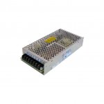
Attachments
Lurking and listening - good thread.
I am watching this with interest as I am 70% through a Rosenblit build and for output tube filament supplies picked up one of these to play with from All electronics. It is adjustable by a couple of volts either way, to get the exact voltage depending on if I have 8, 12 or 16 tubes plugged in, and is smaller and lighter. I figured it would be generally useful somewhere even if I eventually replace it with real iron. Will this thing radiate noise or cause any other nasty effects? Or should I be shopping for transformers?
Dave
“Mean Well #RS-150-24. Input: 100-240Vac. Output: 24Vdc 6.5A. 150W switching power supply. Enclosed vented metal case, 197 x 98 x 38mm. Cooled by free air convection. Short circuit/ overload / over-voltage protection. Adjustable output voltage. Led output indicator. Individually boxed. UL, CSE, TUV, CE.”
Which Rozenblit amp. are you building?
anyone have already built the M-60 ?
and, if i read well, there are 16 output tube each channel, i am right ?
I'm triyng to simulate the schematics by ltspice but i've got only few volts at the output of the driver stage. why ?
if you want i can upload the schematics.
now it's all right
i've made an error drawing lines.
I'm very interested in the version with the 6c33c as i have a lot of those laying around. (last count says 18-units).
anyone have sone practical ideas to implement the dedicated CF for each pair of output tubes ? and which is a good biasing for that tube ? at 135v is something like 300ma ?
Any chance you'd post your spice models?now it's all right
i've made an error drawing lines.
I'm very interested in the version with the 6c33c as i have a lot of those laying around. (last count says 18-units).
anyone have sone practical ideas to implement the dedicated CF for each pair of output tubes ? and which is a good biasing for that tube ? at 135v is something like 300ma ?
Thank you.
Actually Sy, people say it does even though it doesn't because they believe a story. You can't find a single case of adding feedback to a tube amplifier that will result in increased power output at lower impedances.
Sorry but this is confusing two issues, something like this would have earned me an instant fail at university (though that was some years ago
). Feedback does indeed lower the output impedance of the amp, but cannot lower the internal plate resistance of the tube - this is inherent to the tube.Output impedance of a follower is approximately 1/gm, which certainly includes triode followers. This is the driving impedance the speaker sees.
The plate resistance is, however, responsible for the voltage drop inside the tube. Essentially, the maximum voltage you can get on the load of a triode follower is determined by the resistive divider made from B+ in form of the plate resistance and load resistance in series - this will set the clipping point. In triode amps, the ratio of plate and load resistance is what sets the clipping point and the maximum power obtainable from a given B+.
In an OTL amp, the total plate resistance is several times that of the typical 8 ohm load if you want to keep the cost within reason - which means that halving the load reduces the voltage on the load by a bit less than half, while the current only increases a slight amount - resulting in roughly a bit more than half the power on an 8 ohm load. And since you test for maximum power by setting whatever drive you must to get to the edge of clipping, output impedance will have little to do with it.
In the M60, you get 60W output for a set of rather beefy 140V supplies, which means that the peak of the output voltage is 31V, while the rest (about 110V) is dissipated in the tube - so the ratio of load and plate resistance is about 1:3.
Output impedance is the ability of the amp to counteract changes of the load impedance, under normal operating conditions, and it does so by compensating for the changes in the load in an attempt to keep the output voltage constant. The lower the output impedance, the better the amp will be at this. In your example, it would do so by increasing the 'internal' voltage output to compensate for the voltage drop in the 'internal' output impedance. If it is already driven to clipping, there is no more voltage to compensate with!
If you really wanted to check to see that NFB indeed lowers impedance, they you cannot do this at the maximum power. Instead, chose a fixed output well below clipping into your 4 ohm load, say 10V, then observe how much that voltage changes when the load is changed from 4 to 8 to indeed, infinite ohms - with or without feedback. Calculating output impedance from the numbers you get should be sufficiently trivial that I don't need to derive the equations here!
There are a few caveats to this.
Firstly, output impedance will vary with biasing. This should be obvious as the transconductance of the tube changes with current and voltage through it - simple to see from the plate curves. In general gm increases with current, so higher bias will mean lower output impedance.
Secondly, output impedance is not constant and depends on the output voltage. For a fair comparison, current through the load should remain well under twice the bias current, and preferably under 1x the bias current. At the extreme, if any side of the amp cuts off during peaks of the output signal, only one side of the circlotron works so the load only sees half of the output tubes connected to the load, so in theory twice the output impedance. However, OTLs are a bit strange this way as they generally run tubes at high currents so the increase in current demand compensates for loss of gm due toonly half the tubes working.
Thirdly, the lower the output impedance, the more difficult it will be to observe changes when NFB is applied. Also, very low values of NFB applied result in very small changes in output impedance. The only way to get it really obvious is to use a relatively high output impedance amp and apply a high amount of feedback (which also means there should be a high gain reserve).
With regards to the M60, it is perhaps the most simple (and therefore most elegant) way to implement an OTL without sacrificing anything. Totem pole topologies are much more complex and finicky to implement, and you can't really make both halves behave as followers - never mind Vhk problems and tons of bootstrapping, introducing time constants and often electrolytic caps into the mix.
As with any circlotron, bias is actually a simple matter once you realise it's the voltage between the differential driver outputs and the midpoint of the load - this is common for all implementations of this topology.
In the case of the M60, it enables a simple driver in form of a cathode follower, which also gives some A2/AB2 drive capability. The coupling caps can be moved tot he inputs of the follower, made much smaller and thus clipping recovery / blocking distortion becomes a much simpler issue.
Having been under the hood of a not-so-great sounding M60, I do have a couple of complaints.
Firstly, 6AS7 are really not made to work in parallel. Fortunately the russian variants are more forgiving, but (and here is an indication of one of the problems inherent to OTLs in a world where monster tubes are not being made any more) I have observed over 3x variance in tube current through 8 sections of one half of the M60's circlotron output - which is why it did not sound so good. For a 500mA bias, the actual currents ranged from 30 to 100mA, which on the high end violates the maximum dissipation of the triode section in question. There is really no good way to solve this problem except for tube burn-in followed by selection and matching. A comprehensive solution would require separate bias for each triode section, which also means a separate follower for each triode section - clearly not practical at all. Unfortunately, you want high gm tubes for an OTL and such variances are quite normal for these. Using a fresh set of selected tubes put the currents well below a 50% variance and resulted in a much better sounding amp.
The amp in question was an upgraded Mk I and it had points to measure each tubes current, using 1 ohm resistors in the cathodes. Unfortunately they don't really help proper current sharing much, but increasing them to 20-50 ohms or more for any 6AS7 variant to work, would increase output impedance too much. It should be noted that speakers are generally designed with voltage drive (very low amp output impedance) in mind - look at it as one extreme that simplifies calculation, the idea is that all series impedances will be built into the speaker (in form of a crossover network, usually) and thus well controlled by the manufacturer. It could well have been current drive - it is eminently possible to design speakers with no more trade-offs than with voltage drive, BUT you need to know it beforehand. However, if the sepaker is designed to be driven by a 0.1 ohm source impedance, then it is very likely it will not sound the way it was designed being driven by a much higher source impedance. Even so, knowing how the speaker is made and the source impedance of the amp, it is possible to add corrections - in fact, such corrections often do not change things for a low source impedance amp (in fact, may make the speaker easyer to drive in some cases!), but they do add parts, and not cheap ones at that.
An interesting point is wether the M60 operates in class A. Here the choice of a 6AS7 is a very interesting tube because it's not an 'ideal' triode - in the sense you would be looking for to implement single ended triode amps, and indeed would produce a lot of distortion in a SE arrangement. Rather than having nice evenly spaced plate curves, they tend to become more horizontal at higher plate voltages, which means the tube is much more difficult to cut off than turn on. If one looks at the typical 140V / 65mA point on the graph, it happens at around -55V or so at the grid. Since the drivers swing symmetrically when one side gets to 0V, the other will be at -110V or so, at which point the current in the tube with the -110V grid voltage will be cut off, while the current in the tube with 0V bias will be about 450mA.
In an ideal push-pull class A circuit (and the circlotron IS a push-pull circuit - every push-pull variant is made out of two single ended circuits), the bias current is half that of the maximum current, suggesting a perfectly constant gm, i.e. driving voltage to output current law. However, the 6AS7 'imperfect' curves give it an advantage here - the bias current can be considerably reduced from the theoretical requirement, while still not driving either half of the circuit into cut off, meaning a significant lowering of heat dissipation at idle - by a factor of about 3.5 or more. It is considerably more difficult to find a pentode type device (including MOSFETs and BJTs) that would exploit the same principle, especially for high gm devices. This mode of operation is usually termed non-switching class AB, or, perhaps the most similar to what the M60 does, hyperbolic class AB. In theory, as long as the nonlinearity cancels out for any load current and chosen bias point, the output stage operates without distortion. In practice, the trade-off is higher order distortion. Plotting composite curves for the M60's output revelas fairly evenly spaced plate curves, however, they are slightly wavy, rather than almost straight (they would be almost straight if something like a 300B or even a 6S33 was used, but the penalty would be much increased idle dissipation!). It should be said that it is somewhat possible to compensate for this in the driver section (using the same principle), but such arrangements, though nice in theory, have serious problems in practice because of tube tolerances and variations between manufacturers.
Adding a pre-heat and turn-on delay timer as well as DC protect REALLY should be no problem and it certainly would not break the bank - PLEASE do it. For DIY constructions - be absolutely sure to put all output heater transformers on the same fuse. If one side of the output loses heating, you will get the full bias current through your speakers, AND the fuses will NOT blow, and your speaker's coils WILL cook. Much simpler to switch the output stage power supply through a relay - this way it's not in series with the output, but is 'behind' the tubes gm and hidden inside the many orders of magnitude higher plate resistance of the output tubes.
All in all, if I were building an OTL, I can hardly think of a better basis to do it the first time with success, than the M60. Variants are of course possible - like pentode inputs, or pentode/ultralinear outputs (some of these are much easier to do in a circlotron arrangement), solid state CCS for the driver part.
Someone mentioned high gm pentodes, possibly triode strapped. Choosing such tubes is not at all trivial, there are issues involving G2 current in pentode mode, and some of the pentodes, once triode strapped, result in lower gm and/or high Rp, which limits how much current you can get without resorting to A2/AB2 drive, at rather high grid currents (EL/PL504 would be a good example - as well as sweep tubes descended from the 807), which means you may end up with MOSFETs as drivers - themselves not being trivial to drive with something like a cascode or pentode.
Last edited:
Sorry but this is confusing two issues, something like this would have earned me an instant fail at university (though that was some years ago
Output impedance of a follower is approximately 1/gm, which certainly includes triode followers. This is the driving impedance the speaker sees.
The plate resistance is, however, responsible for the voltage drop inside the tube. Essentially, the maximum voltage you can get on the load of a triode follower is determined by the resistive divider made from B+ in form of the plate resistance and load resistance in series - this will set the clipping point. In triode amps, the ratio of plate and load resistance is what sets the clipping point and the maximum power obtainable from a given B+.
In an OTL amp, the total plate resistance is several times that of the typical 8 ohm load if you want to keep the cost within reason - which means that halving the load reduces the voltage on the load by a bit less than half, while the current only increases a slight amount - resulting in roughly a bit more than half the power on an 8 ohm load. And since you test for maximum power by setting whatever drive you must to get to the edge of clipping, output impedance will have little to do with it.
In the M60, you get 60W output for a set of rather beefy 140V supplies, which means that the peak of the output voltage is 31V, while the rest (about 110V) is dissipated in the tube - so the ratio of load and plate resistance is about 1:3.
Output impedance is the ability of the amp to counteract changes of the load impedance, under normal operating conditions, and it does so by compensating for the changes in the load in an attempt to keep the output voltage constant. The lower the output impedance, the better the amp will be at this. In your example, it would do so by increasing the 'internal' voltage output to compensate for the voltage drop in the 'internal' output impedance. If it is already driven to clipping, there is no more voltage to compensate with!
If you really wanted to check to see that NFB indeed lowers impedance, they you cannot do this at the maximum power. Instead, chose a fixed output well below clipping into your 4 ohm load, say 10V, then observe how much that voltage changes when the load is changed from 4 to 8 to indeed, infinite ohms - with or without feedback. Calculating output impedance from the numbers you get should be sufficiently trivial that I don't need to derive the equations here!
There are a few caveats to this.
Firstly, output impedance will vary with biasing. This should be obvious as the transconductance of the tube changes with current and voltage through it - simple to see from the plate curves. In general gm increases with current, so higher bias will mean lower output impedance.
Secondly, output impedance is not constant and depends on the output voltage. For a fair comparison, current through the load should remain well under twice the bias current, and preferably under 1x the bias current. At the extreme, if any side of the amp cuts off during peaks of the output signal, only one side of the circlotron works so the load only sees half of the output tubes connected to the load, so in theory twice the output impedance. However, OTLs are a bit strange this way as they generally run tubes at high currents so the increase in current demand compensates for loss of gm due toonly half the tubes working.
Thirdly, the lower the output impedance, the more difficult it will be to observe changes when NFB is applied. Also, very low values of NFB applied result in very small changes in output impedance. The only way to get it really obvious is to use a relatively high output impedance amp and apply a high amount of feedback (which also means there should be a high gain reserve).
With regards to the M60, it is perhaps the most simple (and therefore most elegant) way to implement an OTL without sacrificing anything. Totem pole topologies are much more complex and finicky to implement, and you can't really make both halves behave as followers - never mind Vhk problems and tons of bootstrapping, introducing time constants and often electrolytic caps into the mix.
As with any circlotron, bias is actually a simple matter once you realise it's the voltage between the differential driver outputs and the midpoint of the load - this is common for all implementations of this topology.
In the case of the M60, it enables a simple driver in form of a cathode follower, which also gives some A2/AB2 drive capability. The coupling caps can be moved tot he inputs of the follower, made much smaller and thus clipping recovery / blocking distortion becomes a much simpler issue.
Having been under the hood of a not-so-great sounding M60, I do have a couple of complaints.
Firstly, 6AS7 are really not made to work in parallel. Fortunately the russian variants are more forgiving, but (and here is an indication of one of the problems inherent to OTLs in a world where monster tubes are not being made any more) I have observed over 3x variance in tube current through 8 sections of one half of the M60's circlotron output - which is why it did not sound so good. For a 500mA bias, the actual currents ranged from 30 to 100mA, which on the high end violates the maximum dissipation of the triode section in question. There is really no good way to solve this problem except for tube burn-in followed by selection and matching. A comprehensive solution would require separate bias for each triode section, which also means a separate follower for each triode section - clearly not practical at all. Unfortunately, you want high gm tubes for an OTL and such variances are quite normal for these. Using a fresh set of selected tubes put the currents well below a 50% variance and resulted in a much better sounding amp.
The amp in question was an upgraded Mk I and it had points to measure each tubes current, using 1 ohm resistors in the cathodes. Unfortunately they don't really help proper current sharing much, but increasing them to 20-50 ohms or more for any 6AS7 variant to work, would increase output impedance too much. It should be noted that speakers are generally designed with voltage drive (very low amp output impedance) in mind - look at it as one extreme that simplifies calculation, the idea is that all series impedances will be built into the speaker (in form of a crossover network, usually) and thus well controlled by the manufacturer. It could well have been current drive - it is eminently possible to design speakers with no more trade-offs than with voltage drive, BUT you need to know it beforehand. However, if the sepaker is designed to be driven by a 0.1 ohm source impedance, then it is very likely it will not sound the way it was designed being driven by a much higher source impedance. Even so, knowing how the speaker is made and the source impedance of the amp, it is possible to add corrections - in fact, such corrections often do not change things for a low source impedance amp (in fact, may make the speaker easyer to drive in some cases!), but they do add parts, and not cheap ones at that.
An interesting point is wether the M60 operates in class A. Here the choice of a 6AS7 is a very interesting tube because it's not an 'ideal' triode - in the sense you would be looking for to implement single ended triode amps, and indeed would produce a lot of distortion in a SE arrangement. Rather than having nice evenly spaced plate curves, they tend to become more horizontal at higher plate voltages, which means the tube is much more difficult to cut off than turn on. If one looks at the typical 140V / 65mA point on the graph, it happens at around -55V or so at the grid. Since the drivers swing symmetrically when one side gets to 0V, the other will be at -110V or so, at which point the current in the tube with the -110V grid voltage will be cut off, while the current in the tube with 0V bias will be about 450mA.
In an ideal push-pull class A circuit (and the circlotron IS a push-pull circuit - every push-pull variant is made out of two single ended circuits), the bias current is half that of the maximum current, suggesting a perfectly constant gm, i.e. driving voltage to output current law. However, the 6AS7 'imperfect' curves give it an advantage here - the bias current can be considerably reduced from the theoretical requirement, while still not driving either half of the circuit into cut off, meaning a significant lowering of heat dissipation at idle - by a factor of about 3.5 or more. It is considerably more difficult to find a pentode type device (including MOSFETs and BJTs) that would exploit the same principle, especially for high gm devices. This mode of operation is usually termed non-switching class AB, or, perhaps the most similar to what the M60 does, hyperbolic class AB. In theory, as long as the nonlinearity cancels out for any load current and chosen bias point, the output stage operates without distortion. In practice, the trade-off is higher order distortion. Plotting composite curves for the M60's output revelas fairly evenly spaced plate curves, however, they are slightly wavy, rather than almost straight (they would be almost straight if something like a 300B or even a 6S33 was used, but the penalty would be much increased idle dissipation!). It should be said that it is somewhat possible to compensate for this in the driver section (using the same principle), but such arrangements, though nice in theory, have serious problems in practice because of tube tolerances and variations between manufacturers.
Adding a pre-heat and turn-on delay timer as well as DC protect REALLY should be no problem and it certainly would not break the bank - PLEASE do it. For DIY constructions - be absolutely sure to put all output heater transformers on the same fuse. If one side of the output loses heating, you will get the full bias current through your speakers, AND the fuses will NOT blow, and your speaker's coils WILL cook. Much simpler to switch the output stage power supply through a relay - this way it's not in series with the output, but is 'behind' the tubes gm and hidden inside the many orders of magnitude higher plate resistance of the output tubes.
All in all, if I were building an OTL, I can hardly think of a better basis to do it the first time with success, than the M60. Variants are of course possible - like pentode inputs, or pentode/ultralinear outputs (some of these are much easier to do in a circlotron arrangement), solid state CCS for the driver part.
Someone mentioned high gm pentodes, possibly triode strapped. Choosing such tubes is not at all trivial, there are issues involving G2 current in pentode mode, and some of the pentodes, once triode strapped, result in lower gm and/or high Rp, which limits how much current you can get without resorting to A2/AB2 drive, at rather high grid currents (EL/PL504 would be a good example - as well as sweep tubes descended from the 807), which means you may end up with MOSFETs as drivers - themselves not being trivial to drive with something like a cascode or pentode.
what do you think about using 6c33c in the m60 ?
- Home
- Amplifiers
- Tubes / Valves
- What tubes for a OTL tube amp?