ok, fair enough.
Another interesting part is the ease of which you can change transformer as well.
In my case this thread started with me looking for a 20 or so W amp.
The AN-4450 will no doubt drive 4 tubes, probably 6 as well and possibly even 8?
I guess I could do it that way?
Go for the smaller one and start off with 4 tubes. If there's an output impedance issue or poweer issue I can add tubes and if Things get really bad it's easy enough to change transformers.
It truly is a super desig with its modularity.
MarkusG,
Yes, I believe the modular flexibility of the Balanced-Differential Circlotronic topology can be leveraged exactly as you've outlined. If I've done the math correctly, four 6AS7's per channel should yield about 23-watts of output power into an 8-ohm load. The AN-4450 power-transformer should readily handle this load (and likely more...
 ). Just leave physical space in your chassis design to accommodate the potential inclusion of additional pairs of output tubes and slightly larger power-transformers (should you opt to increase power output). The deceptive simplicity of this elegant topology is intellectually captivating; I can't wait to hear how it sounds...
 IMO a little extra current in the transformer is not a bad idea. Here's how I figure it:
60Watts=8ohms X Isquared => I= a little less than 2.8 (I'm using my desktop caluculator)
2.8/2 = 1.4A... this is the maximum that the amp can draw under full power per phase, assuming 8 6AS7Gs. I like a 1.5A/winding transformer for the job, assuming its rated for continuous duty. Higher current ratings will give you less voltage sag due to resistive losses in the windings so is not a bad idea. We're not regulating the output supplies so the lower impedances will be helpful. That's why I go for bigger filter banks too.
IMO a little extra current in the transformer is not a bad idea. Here's how I figure it:
60Watts=8ohms X Isquared => I= a little less than 2.8 (I'm using my desktop caluculator)
2.8/2 = 1.4A... this is the maximum that the amp can draw under full power per phase, assuming 8 6AS7Gs. I like a 1.5A/winding transformer for the job, assuming its rated for continuous duty. Higher current ratings will give you less voltage sag due to resistive losses in the windings so is not a bad idea. We're not regulating the output supplies so the lower impedances will be helpful. That's why I go for bigger filter banks too.
atmasphere,
Thank you; we greatly appreciate your empirical observations as to the functional requirements for the output-stage power-supplies! It makes sense that increasing the current capacity of the power-transformers and bulking-up the capacitor banks would decrease the "sag" in the voltage and lower the power-supply impedance.
OK, the controversy is at an end; any of the Antek AN-x450 series of power transformers are usable for powering the M-60 output stage "floating" power-supplies.
All transformers in this product series provide the 50VAC+50VAC dual-secondary configuration necessary to provision the 140VDC voltage. The smallest unit, the AN-4450, is rated for 4A continuous output; the largest unit in the series, the AN-15450, will deliver a massive 15A! So, scaling-up the output stage can be easily accommodated, but you would need to beef-up the driver stage (as in the Atmasphere MA-1 through MA-3 power-amplifiers) in order to cleanly drive the phalanx of 6AS7's that could support that level of output current delivery! Ok, cool. So We're good to go with the AN-4450?
I have another little detail or two that I'm curious about.
What's the purpose of the 0.1uF cap on the V4 input?
And how come the inputs #2(+) and #3(-) are wired directly to the +/- outputs (speaker posts)? What's the purpose of doing that?
I have another little detail or two that I'm curious about.
What's the purpose of the 0.1uF cap on the V4 input?
And how come the inputs #2(+) and #3(-) are wired directly to the +/- outputs (speaker posts)? What's the purpose of doing that?
Ok, cool. So We're good to go with the AN-4450?
Yes, the AN-4450 will "work". If you want lower power-supply impedance and quicker capacitor-bank recharge rates, you can select one of the higher-current 50+50VAC models in the Antek AN-xx450 series of power-transformers.
I have another little detail or two that I'm curious about.
What's the purpose of the 0.1uF cap on the V4 input?
The pair of 0.1uF capacitors couple the differential output of the input stage (V1-V3) to the inputs of the driver stage (V4). This pair of capacitors are the only point at which the M-60 signal-path directly passes through any signal capacitors, so these capacitors are critical in maintaining the signal integrity. The factory-upgrade option is to use V-Cap Teflon capacitors (http://www.v-cap.com/products.php); the TFTF (Tin Foil Teflon Film) capacitors have been acknowledged as the most audibly-transparent, but I see that V-Cap has "upped-the-ante" with a new CuTF (Copper Foil Teflon Film) capacitor, for which they claim that they've "raised the bar", again...
And how come the inputs #2(+) and #3(-) are wired directly to the +/- outputs (speaker posts)? What's the purpose of doing that?
The differential outputs are fed-back to the input differential pair via the 2M-ohm feedback resistors; there is no direct connection between the inputs/outputs.
Last edited:
Missed the the 2M resistors... and ok it's a feed back thing.
The reason I was wondering about the caps are one often use caps to deal with dc but iirc the circlotron is supposed to do that as well due to the design? It's been said so much that I'm having trouble keeping everything straight.
I'm curious by nature...
The reason I was wondering about the caps are one often use caps to deal with dc but iirc the circlotron is supposed to do that as well due to the design? It's been said so much that I'm having trouble keeping everything straight.
I'm curious by nature...
One of the beauties of the Circlotron is that you can set the output to any voltage level- ground is a nice voltage level so that's what we are doing with it.
But the **input** to the circuit is another matter! The tubes need to be biased, so the voltage on their grids is negative, like you see with any conventional amplifier.
However we are driving the tubes with a direct-coupled cathode follower. The CF itself is going to have its grids be somewhat negative with respect to the cathodes of the tubes, hence there is a negative voltage there as well (in practice about 6-8V more negative than the cathodes). OTOH the plates of V2 are at about 150-200V, so we do have to block the DC voltage. The nice thing here is that the timing constants are easy to manage as the input impedance of the CF is quite high, so 0.1uf is plenty. You can do quite well with 0.047uf too- IMO, the smaller you can do it without compromising bass performance the better. That value does seem to come out at 0.1uf ideally.
One of the beauties of the Circlotron is that you can set the output to any voltage level- ground is a nice voltage level so that's what we are doing with it.
But the **input** to the circuit is another matter! The tubes need to be biased, so the voltage on their grids is negative, like you see with any conventional amplifier.
However we are driving the tubes with a direct-coupled cathode follower. The CF itself is going to have its grids be somewhat negative with respect to the cathodes of the tubes, hence there is a negative voltage there as well (in practice about 6-8V more negative than the cathodes). OTOH the plates of V2 are at about 150-200V, so we do have to block the DC voltage. The nice thing here is that the timing constants are easy to manage as the input impedance of the CF is quite high, so 0.1uf is plenty. You can do quite well with 0.047uf too- IMO, the smaller you can do it without compromising bass performance the better. That value does seem to come out at 0.1uf ideally.
atmasphere,
Excellent! The additional design details certainly help to fill-in-the-blanks! I had assumed that the Class-A2 Circlotron output stage would require a very low-impedance, DC-coupled or transformer-coupled driver stage. The more conventional AC-coupled driver stages would not allow grid current flow, which is required for Class-A2 operations.
Have you had an opportunity to evaluate the new V-Cap CuTF (Copper Foil Teflon Film) coupling capacitors? The previous V-Cap high-watermark product, the TFTF (Tin Foil Teflon Film) capacitors, have certainly been impressive in the projects in which I've installed them, so I'd be very interested in your opinion of the relative merits of these components.
Last edited:
The penny finally droped for me.
I've been looking at things the wrong way and now everything is looking much clearer.
What would the result be if you cut the feedback all togeather? Instead of having the 2M resistors you removed it?
And the 5k pot on the V4 grid bias, is that for controlling the channel balance? I just noticed how it was connected...
The penny finally droped for me.
I've been looking at things the wrong way and now everything is looking much clearer.
What would the result be if you cut the feedback all togeather? Instead of having the 2M resistors you removed it?
Running the M-60 in open-loop mode (2M-ohm feedback resistors disconnected) is Atma-Sphere's preferred/recommended configuration. The closed-loop mode only applies about 1dB of NFB to the circuit.
And the 5k pot on the V4 grid bias, is that for controlling the channel balance? I just noticed how it was connected...
The 5K-ohm potentiometer is used for setting the DC-offset between output terminals within a single channel of the output stage. The 5K-ohm pot is not connected between channels; remember, this is a mono-block power-amplifier.
Last edited:
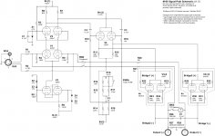
M-60 OTL Signal-Path Schematic Schematic (v1.0)
I'm posting the M-60 signal-path schematic which includes the various alterations discussed in this DIY M-60 thread. I had to "zip" the PDF document to squeeze it down to the forum's filesize limit. Please review and let me know if I left anything out or screwed anything up...
I'm posting the M-60 signal-path schematic which includes the various alterations discussed in this DIY M-60 thread. I had to "zip" the PDF document to squeeze it down to the forum's filesize limit. Please review and let me know if I left anything out or screwed anything up...
Increased Input Stage Bias - The bias-control resistor, R8, in conjunction with the Zener diodes, Z4-Z5, set the bias current for the input stage. R8 has been reduced in value from 37.4K-ohms to 18.2K-ohms, which increases the input stage total bias current to about 5mA (2.5mA per side of the input differential pair).
Adjusted Input Stage Plate Resistors - To compensate for the increased current flow in the input-stage differential pair, the plate resistors, R6-R7, have been reduced in value to 50K-ohms in order to maintain the same voltage drop across the plate resistors.
Negative Feedback Loop Open/Close Switch - Switch, SW4, has been included in the schematic to enable the end-user to enable/disable the NFB; closing the switch provides about 1dB of negative feedback, while opening the switch runs the circuit in open-loop mode
Increased Output Tube Cathode Resistor Value - Atma-Sphere Music Systems recommended 5-ohm cathode resistors to minimize "current-hogging" between the paralleled 6AS7 output tubes as well as to improve distortion characteristics of the circuit.
Attachments
Yeah, that' s what I meant to say but I chose poor wording.
Only good news today, cutting the feedback definately appeals to my esthetic sense.
I just posted the cumulative M-60 thread signal-path schematic, which includes an NFB engage/disengage switch. Where feasible, you can run the circuit in open-loop mode, but you'll have the option of running in closed-loop mode when it may be desirable (such as dropping the output impedance to drive a difficult/ill-behaved loudspeaker load).
For some reason a lot of people want to try to make their tube amplifier drive really low impedances, which is actually a Bad Idea. Its like trying to put really cheap tires on a really nice sports car: you will never be able to realize the performance as a result.
It turns out though that even with transistors higher impedances in the load are important if sound quality is the goal, IOW if sound quality is your goal then use a higher impedance! If you *are* running a higher impedance, like 16 ohms the M-60 will make about 80 watts and you will have no need at all for the feedback. If you are using a lower impedance speaker (4 ohms or less) consider getting a set of ZEROs (Autoformers offered by ZeroImpedance- Improve your speaker sound quality with the use of an autoformer.) rather than using the feedback.
An interesting fact about feedback: it does not lower output impedance even though people say it does. How do I know this? The power output of this amplifier is unchanged into 4 ohms whether it has zero feedback or 20db. What is different is how the amp tries to respond to the load; it will limit itself to the 40 watts it can make into 4 ohms. Now if NFB **did** lower output impedance, then the 4 ohm power figure would go up. IOW the method of measuring output impedance wherein NFB is seen to reduce the output impedance is really a means of measuring the servo gain, not the actual impedance.
Fire away...
Interesting...
First we build an OTL amp then we hook up a trafo. It feels so wrong even though I do understand the arguments.
The zeros are .3ohms @ 12AWG, running the numbers I get close to 189' of wire inserted between the amp and the speaker. (only wire resistance used for calculations)
Otoh there's a lot of wire in the speaker coils as well so...
@ $450 a pop it's somewhat of an expensive experiment.
It does however make speaker cables redundant, at least that's something.
For some reason a lot of people want to try to make their tube amplifier drive really low impedances, which is actually a Bad Idea. Its like trying to put really cheap tires on a really nice sports car: you will never be able to realize the performance as a result.
I already own a pair of Zero autoformers; they've been quite helpful in allowing me to successfully interface my various vacuum-tube amplifiers with some pretty silly loudspeaker loads...
It turns out though that even with transistors higher impedances in the load are important if sound quality is the goal, IOW if sound quality is your goal then use a higher impedance! If you *are* running a higher impedance, like 16 ohms the M-60 will make about 80 watts and you will have no need at all for the feedback. If you are using a lower impedance speaker (4 ohms or less) consider getting a set of ZEROs (Autoformers offered by ZeroImpedance- Improve your speaker sound quality with the use of an autoformer.) rather than using the feedback.
Obviously, I've just begun to order all of the pieces/parts necessary to begin construction on my M-60-based headphone-amp/line-stage, so I have no practical/operational experience with the balanced-differential Circlotron OTL. But, from a theoretical standpoint, I like the idea of the Zero autoformer keeping the impedence presented to the amplifier above a rational threshold, thereby allowing the M-60 to stay in Class-A2 mode when presented with inappropriate loads.
An interesting fact about feedback: it does not lower output impedance even though people say it does. How do I know this? The power output of this amplifier is unchanged into 4 ohms whether it has zero feedback or 20db. What is different is how the amp tries to respond to the load; it will limit itself to the 40 watts it can make into 4 ohms. Now if NFB **did** lower output impedance, then the 4 ohm power figure would go up. IOW the method of measuring output impedance wherein NFB is seen to reduce the output impedance is really a means of measuring the servo gain, not the actual impedance.
I included the feedback engage/defeat switch in response to requests. I intend to run mine open-loop...
Fire away...
Not me; this project looks pretty cool...
Interesting...
First we build an OTL amp then we hook up a trafo. It feels so wrong even though I do understand the arguments.
The zeros are .3ohms @ 12AWG, running the numbers I get close to 189' of wire inserted between the amp and the speaker. (only wire resistance used for calculations)
Otoh there's a lot of wire in the speaker coils as well so...
@ $450 a pop it's somewhat of an expensive experiment.
It does however make speaker cables redundant, at least that's something.
Hmmm.... Did your calculations take into account that the Zero's are autoformers, not transformers. With the autoformer, there's just a single multi-tap winding.
An interesting fact about feedback: it does not lower output impedance even though people say it does. How do I know this? The power output of this amplifier is unchanged into 4 ohms whether it has zero feedback or 20db. What is different is how the amp tries to respond to the load; it will limit itself to the 40 watts it can make into 4 ohms. Now if NFB **did** lower output impedance, then the 4 ohm power figure would go up. IOW the method of measuring output impedance wherein NFB is seen to reduce the output impedance is really a means of measuring the servo gain, not the actual impedance.
Fire away...
People say it does because it does. There's a difference between lowering output impedance and increasing max current delivery.
- Home
- Amplifiers
- Tubes / Valves
- What tubes for a OTL tube amp?