Any chance you'd post your spice models?
Thank you.")
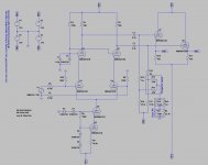
as promised, here the ltspice schematics, this is only the driver stage...
but it still doesn't working right (i guess)... the voltage swing is very low on the output.
Where i'm wrong ?
Attachments
what do you think about using 6c33c in the m60 ?
I guess you mean using 6S33S in a topology like the M60? Well, the 6S33S is THE russian tube for OTLs so it is certainly usable, but not easily.
Pro:
- In theory you need 2 6S33S to replace 4 6AS7G, if the 6S33S are operated with both cathodes. But t his comes at a price (see below).
- Using two tubes per side makes it practical to double up the driver stage followers and provide separate bias for each tube. This makes it easier to balance the current through the tubes.
Cons:
- 2 6S33S will make nearly 90W of heat only on account of heaters. In contrast, 4 6AS78 will make 60W of heat.
- 2 6S33S can dissipate a maximum of 120W whereas 4 6AS7 can dissipate a maximum of 104W. However, in these circumstances, total heat dissipation will be 210W for two 6S33S and 164W for four 6AS7 - in the latter case it will be distributed into 4 sockets, while it will be two sockets for the 6S33S - meaning a lot of heat concentrated in less space. In reality, 6S33S benefit greatly from forced cooling when used like this, and it is particulairly important to get good sockets.
- It is very difficult to burn-out internal connections in the 6S33S. They will not act as a fuse.
- two 6S33S have substanbtially higher Rp than four 6AS7, meaning you may end up with less power output from the same power supply voltage - meaning, higher losses. It is easy to run out of available anode dissipation this way even if it is higher for two 6S33S, or you may have to lower bias and operate in class AB.
- 6S33S have rather large variances of parameters, and you get a good idea what they are only after initial burn-in. This is why separate biasing is a must. However, the comprehensive solution would be to implement separate AC drive balance as well - otherwise you still need to select tubes for optimum results. And, it is more difficult to find two pairs out of 4 tubes than two quartets out of 8 tubes - there are less combinations among which to chose the optimum.
- 6S33S like to do grid current when Vgk approaches zero, and can even go into runaway at the limits of power dissipation. Fortunately, driving them from a direct-coupled follower solves 99.9% of that. However, driving them heavily into A(B)2 is not a good idea at high dissipation because you can easily cause the grids to overheat.
All in all, if you want to get the same results as the M60, the sure way is to use 3 6S33S per side. You also get substantially lower output impedance, bisas more heavily into class A, but you pay for it with twice the heater power, a somewhat more complex driver, and more costly tubes.
For a smaller OTL amp, you could do what atmasphere does, five 6AS7 per channel, and perhaps save one 6SN7 by using a good cascoded solid state current source. If you got really adventurous, you could use two triode-pentodes (pentodes to form the input differential instead of cascodes) and a solid state current source to reduce the number of bulbs in the driver to just two - but your tube choices might be a bit odd as you need a relatively small pentode and beefyer triode rather than the usual small triode and beefy pentode combination.
as promised, here the ltspice schematics, this is only the driver stage...
but it still doesn't working right (i guess)... the voltage swing is very low on the output.
Where i'm wrong ?
Yea!! Thank you for sharing.
Please keep us in the loop as you work it out and the 6c33 tubes as well!
Having the opportunity to learn is what makes these threads Great!
I guess you mean using 6S33S in a topology like the M60? Well, the 6S33S is THE russian tube for OTLs so it is certainly usable, but not easily.
Pro:
- In theory you need 2 6S33S to replace 4 6AS7G, if the 6S33S are operated with both cathodes. But t his comes at a price (see below).
- Using two tubes per side makes it practical to double up the driver stage followers and provide separate bias for each tube. This makes it easier to balance the current through the tubes.
Cons:
- 2 6S33S will make nearly 90W of heat only on account of heaters. In contrast, 4 6AS78 will make 60W of heat.
- 2 6S33S can dissipate a maximum of 120W whereas 4 6AS7 can dissipate a maximum of 104W. However, in these circumstances, total heat dissipation will be 210W for two 6S33S and 164W for four 6AS7 - in the latter case it will be distributed into 4 sockets, while it will be two sockets for the 6S33S - meaning a lot of heat concentrated in less space. In reality, 6S33S benefit greatly from forced cooling when used like this, and it is particulairly important to get good sockets.
- It is very difficult to burn-out internal connections in the 6S33S. They will not act as a fuse.
- two 6S33S have substanbtially higher Rp than four 6AS7, meaning you may end up with less power output from the same power supply voltage - meaning, higher losses. It is easy to run out of available anode dissipation this way even if it is higher for two 6S33S, or you may have to lower bias and operate in class AB.
- 6S33S have rather large variances of parameters, and you get a good idea what they are only after initial burn-in. This is why separate biasing is a must. However, the comprehensive solution would be to implement separate AC drive balance as well - otherwise you still need to select tubes for optimum results. And, it is more difficult to find two pairs out of 4 tubes than two quartets out of 8 tubes - there are less combinations among which to chose the optimum.
- 6S33S like to do grid current when Vgk approaches zero, and can even go into runaway at the limits of power dissipation. Fortunately, driving them from a direct-coupled follower solves 99.9% of that. However, driving them heavily into A(B)2 is not a good idea at high dissipation because you can easily cause the grids to overheat.
All in all, if you want to get the same results as the M60, the sure way is to use 3 6S33S per side. You also get substantially lower output impedance, bisas more heavily into class A, but you pay for it with twice the heater power, a somewhat more complex driver, and more costly tubes.
For a smaller OTL amp, you could do what atmasphere does, five 6AS7 per channel, and perhaps save one 6SN7 by using a good cascoded solid state current source. If you got really adventurous, you could use two triode-pentodes (pentodes to form the input differential instead of cascodes) and a solid state current source to reduce the number of bulbs in the driver to just two - but your tube choices might be a bit odd as you need a relatively small pentode and beefyer triode rather than the usual small triode and beefy pentode combination.
Whoa!!!! Now here is "the Bee's knees" and a whopper of educational opportunity....
THANK YOU, THANK YOU!!!
Would you care to deliver a similar dissertation with respect to the 6C19P triodes?
Though one realizes the above quoted does have the basis lain.
Now one had rather best slink back to the rear of the class and remain thoughtfully, gratefully, quiet!!
Well, if you truly want the lowdown od 6S33 and it's predecessors (6S19 is sort of half of a 6S33), there is one person that comes to mind with a wealth of knowledge on this subject. Look here:
Description
Description
My experience has been that the 6C33 eats sockets. Not right away, but if you use the Russian or Chinese socket you will be tightening the filament contact on the socket after about 2000 hours in order to keep the tube lit. After 5000-7000 hours the socket will have to be replaced.
I don't know about you, but the idea of rebuilding the output section every so often isn't that appealing. By contrast the octal sockets for the 6AS7 will last 30-40 years if not a lot longer.
If you really are set on 6C33s, you have to use Teflon/silver wire! Cooper will not hold up as the insulation will get to hot and will perish quickly. Obviously you have to plan for good layout for cooling. Forced air is not a bad idea.
Anytime a 6C33 appears in an amplifier, there should be a fuse associated with it as well. 1.5Amps seems to be sufficient- when the fuse blows its usually an indication that the tube is at the end of its service life, regardless of how long that has been. Once they start arcing, they are likely to keep it up.
I guess you mean using 6S33S in a topology like the M60? Well, the 6S33S is THE russian tube for OTLs so it is certainly usable, but not easily. ...
IRFP460 don't need any sockets, and last forever.
6C33C is not a tube for OTL, it is a tube for VR in military avionics.
i think he mean that is the best tube to be suited in a otl amplifier, not the tube WAS BORN for OTL.
anyway, i still unable to run the spice simulation of the driver right. Can you checks my work ?
IRFP460 don't need any sockets, and last forever.
-plus sounds terrible, so forever is a really long time
, and really off-topic.I am in agreement about the 6C33 not being for OTLs (just like 6SN7s and wire are not 'for' OTLs, but both seem to serve), and the exact same thing can be said of 6AS7Gs. They work fine in OTL circuits; the 6C33 does too, limited by its socket, which is also a problem in VR service. The Russian spec sheet called for a 750 hour service life, after which the socket was replaced as well.
In the old days, whenever we got a 6C33, it came in a box with the replacement socket. It took a while for the importer to figure out that he could remove the socket and charge separately for it.
My experience has been that the 6C33 eats sockets. Not right away, but if you use the Russian or Chinese socket you will be tightening the filament contact on the socket after about 2000 hours in order to keep the tube lit. After 5000-7000 hours the socket will have to be replaced.
I don't know about you, but the idea of rebuilding the output section every so often isn't that appealing. By contrast the octal sockets for the 6AS7 will last 30-40 years if not a lot longer.
If you really are set on 6C33s, you have to use Teflon/silver wire! Cooper will not hold up as the insulation will get to hot and will perish quickly. Obviously you have to plan for good layout for cooling. Forced air is not a bad idea.
Anytime a 6C33 appears in an amplifier, there should be a fuse associated with it as well. 1.5Amps seems to be sufficient- when the fuse blows its usually an indication that the tube is at the end of its service life, regardless of how long that has been. Once they start arcing, they are likely to keep it up.
thanks for the advice... i'll keep in mind.
I've already choosen a forced ventilation and i've got some good quality septal socket in teflon.
i'm thinking on using 150v on the anodes of the 6c33c and a bias of 200ma each tube. what do you think ?
anyway, i still unable to run the spice simulation of the driver right. Can you checks my work ?
Can you post the schematic you are using?
Sorry but this is confusing two issues, something like this would have earned me an instant fail at university (though that was some years ago
If you really wanted to check to see that NFB indeed lowers impedance, they you cannot do this at the maximum power. Instead, chose a fixed output well below clipping into your 4 ohm load, say 10V, then observe how much that voltage changes when the load is changed from 4 to 8 to indeed, infinite ohms - with or without feedback. Calculating output impedance from the numbers you get should be sufficiently trivial that I don't need to derive the equations here!
ilimzn, I think you missed a comment I made, which is this:
IOW pretty much the same thing you are commenting on. What I was commenting on was the very phenomena you are pointing to in your last paragraph above. We're on the same page, but use different nomenclature as I don't subscribe to the Voltage Paradigm vernacular- its too confusing for the layman, although in this case I think your explanation is better. What is amusing to me is that we have different conclusions from the same explanationWhat is different is how the amp tries to respond to the load; it will limit itself to the 40 watts it can make into 4 ohms.
So- is that like, a 'no' then?here you are.
So- is that like, a 'no' then?
mhhh, no, is so like i have don't hit the attach button
Attachments
thanks for the advice... i'll keep in mind.
I've already choosen a forced ventilation and i've got some good quality septal socket in teflon.
i'm thinking on using 150v on the anodes of the 6c33c and a bias of 200ma each tube. what do you think ?
The tube will certainly handle the voltage. I would try 200ma and see how it goes. It won't be class A, but OTLs are relatively immune to switching issues, so you won't suffer. In recent years I've really been thinking that class A like we used to do on these tubes is inappropriate due to the amazing amount of heat. 6C33s run so hot that the bulb surface will cause instant burns and its not good for sockets, wire or solder either.
The schematic is OK. Either your not putting B+ and B- to it (they have to be equal but opposite 300V) or something is wrong with your models or the like in Spice. You should be able to get about 200V swing at the output of the CF.mhhh, no, is so like i have don't hit the attach button
The schematic is OK. Either your not putting B+ and B- to it (they have to be equal but opposite 300V) or something is wrong with your models or the like in Spice. You should be able to get about 200V swing at the output of the CF.
i'm supplying voltage trought vb1/vb2/vb3/vb4, where vb1/vb2 are +/- 325v and vb3/vb4 are +/- 310v
i've checked on the point where i put the voltage and there are ok..
tha anode of the upper 6sn7 (U1) is at 190v, the tube that take the signal-in (U3) is at 52v and the lower one, the CCS, (U5) at 0.8v.
i think the model is ok...
What is on the anode of V4? It should be about 260V.
- Home
- Amplifiers
- Tubes / Valves
- What tubes for a OTL tube amp?