Starting to go further and further from minimal visual impact!
Indeed! I'm still pondering the idea of a smaller baffle, similar to the original size that resulted in a QTc ~ 0.9 and then building in more volume in the wall. I'm considering a series of holes that go to the space between the studs that would balance the strength of the wall with the free flow of air. Thinking ~2" holes behind every driver so the back wave has another place to go. It would be easy to adjust the volume if I wanted to experiment as well. Also, I was thinking about using a layer of MVL or perhaps some of that Green Glue that's used to sound proof rooms between the drywall and the plywood.
Here's a sketch (I really need to learn SketchUp at some point):
Last edited:
HDMI is a good option if your AVR has it, as you should be able to EQ the channels in Jriver separately before they are sent to the AVR.
Ah, I see. That's super helpful to see the screen shot. Unfortunately, my old MacBook pro doesn't have HDMI. Would a thunderbolt to HDMI adapter do the same thing?
Do you use Wine to run DRC on your MacBook to generate convolution filters? I'm considering getting an Intel NUC or something similar instead. PC version of JRiver seems to be a little better overall. It has HDMI output. And it's nice and small.
Is there any guidance or theory behind the size/shape of the wings? I could use thin kerfs in MDF to make the curves. Or I can approximate with 3-5 segments.
I've been reading a lot about horn theory and am in no way an expert on this subject, but corner loading is somewhat similar to horn loading! I'm still learning this stuff as well, so don't take the following for fact, it's merely an observation.
Picture a wave front (frequency dependent) expanding from the corner loaded line array. Generally speaking, the wave front (at lower frequencies) will be perpendicular to the baffle/wall surface. If the baffle to wall interface is concave then the wave front would be a more planar shape as it leaves the drivers and would transition to a cylindrical shape as it expands and gets further away from the drivers. If the baffle to wall interface is convex then the wave front would be more cylindrical until it encounters the discontinuity. This will cause diffraction. Based on this line of thought, it would make more sense to have a concave transition from baffle to wall, not a convex transition similar to a front loaded horn.
Indeed! I'm still pondering the idea of a smaller baffle, similar to the original size that resulted in a QTc ~ 0.9 and then building in more volume in the wall. I'm considering a series of holes that go to the space between the studs that would balance the strength of the wall with the free flow of air. Thinking ~2" holes behind every driver so the back wave has another place to go. It would be easy to adjust the volume if I wanted to experiment as well. Also, I was thinking about using a layer of MVL or perhaps some of that Green Glue that's used to sound proof rooms between the drywall and the plywood.
Here's a sketch (I really need to learn SketchUp at some point):
You could do that, I think the result would be unpredictable and having 2L per driver would not be my no1 priority. Isolating the baffle from the wall would be.
Why don't you make up some triangles of card in different sizes and actually put them in the corner to get a better idea of what the different sized enclosures would look like.
PS I would also look at downloading a copy of Fusion 360, it is a semi cloud based 3D program that is very similar to Inventor or Solidworks. It is free for non commercial use and I used it to produce the 3D model of my enclosure. I had never used it before so it isn't that hard to learn. There are plenty of tutorials and it works in a very similar way to solidworks, so if you have ever seen how solidworks functions you would be off to a good start.
Last edited:
How's this for shape?
I like to keep things simple.
It's asymmetrical, which is a good thing, and probably will get you your 2 litres needed per driver. Stuff the inside well.
Easy to build, one baffle panel, and one extra "dowel" or side stick, with stuffing inside, shaped to follow the cone extension and ease the way to the side wall.
That would be my approach to wall corner based line arrays.
Having the drivers at 45 degrees like in your drawings, it would probably accentuate the "headphone" effect provided by the arrays. By going a bit more relaxed angle, it might widen things a bit better.
Attachments
Last edited:
Assuming that if you mount the driver at/in/behind the corner there will be no discontinuity, it follows that the further from this point you start the greater the compromise (unless you build a completely freestanding one).So something like one of these?
Firstly, the front (baffle/guide) and rear (enclosure) have independent needs and how you manage the rear with the driver so close to the corner is another story.
You could at least protect the highs by holding them straight then releasing them slowly by controlled diffraction after the wavefront has 'matured'. The throat size, angle, mouth size before roundover and roundover radius all need to be decided upon.
Also, the lows should be able to go through and past the waveguide, the distance of its walls from the room walls will become acoustically small at some frequency so this can also be considered. It becomes somewhat complex but you should be able to arrive at values that give you some overlap in needs.
Attachments
Probably, weird that you have thunderbolt but not hdmi. Mine is the right side next to the SD card slot.Ah, I see. That's super helpful to see the screen shot. Unfortunately, my old MacBook pro doesn't have HDMI. Would a thunderbolt to HDMI adapter do the same thing?
Do you use Wine to run DRC on your MacBook to generate convolution filters? I'm considering getting an Intel NUC or something similar instead. PC version of JRiver seems to be a little better overall. It has HDMI output. And it's nice and small.
I have not run any form of room correction so far, I will get to it when the lines are finished as they will benefit from it and I will need to do extensive measurements and EQ anyway.
I don't like WINE but I do use Virtualbox on the Macbook as I mentioned before to allow me to run basic windows programs while sitting on the couch!
I have also used remote desktop that allows you to login to a windows computer and use the screen and keyboard etc. to control it.
I have a NUC and I really like it. There is a range of models to suit the processing power that you need. Unless you plan to try and upsample everything to DSD or something then any of them should be good enough.
Jriver on windows would be a smart choice then you definitely have a hdmi port.
DRC works under Wine. The newer versions of Wine work quite well. Almost anything Audio kind of tests will run in Wine.
So far, I have DRCDesigner, DATS, Edge, and XSim working fine under Wine.
I also use VirtualBox for some programs, but it feels a bit more sluggish for some easy to do calculations... VB is my last resort when I can't get stuff working under Wine.
The advantages of running JRiver on a PC is the Audio driver that takes over anything audio. Any software can use JRiver's output and as such, can add EQ, Convolution, etc and see the effects with programs like REW, APLTDA, etc...
It's a bit harder on a Mac, but doable with AULab and Soundflower.
I was looking at something like the Acer One, or the Asus Vivobook to use as a music server/processor for JRiver. It has integrated screen and probably enough power to do some EQ and convolution.
If not, this mini computer sporting ALC283 audio might do the trick:
ECS - LIVA X Mini PC
Probably, weird that you have thunderbolt but not hdmi. Mine is the right side next to the SD card slot.
I have the generation before the HDMI port showed up next to the SD card slot. Still have the optical drive too. My wife has the newer one though. So theoretically, I can use hers but she probably doesn't want it monopolized by my audio stuff. Thunderbolt to HDMI should work though. And as Perceval mentioned, DRC works with Wine, AU Lab, and Soundflower work so I'll give it a go with what I have before spending money. My computer skills are only so-so though and I may end up getting frustrated enough to just spring for the NUC or something similar.
You could do that, I think the result would be unpredictable and having 2L per driver would not be my no1 priority. Isolating the baffle from the wall would be.
Why don't you make up some triangles of card in different sizes and actually put them in the corner to get a better idea of what the different sized enclosures would look like.
I priced out some custom cut 1/4" aluminum 4" wide by 93" long. Two pieces delivered would be $135 which isn't too bad. I could potentially get them locally for less. I might go through a few hole saws but something to consider as the baffle size to strength ratio obviously improves and it gives me some other options for isolating the baffle from the wall.
To your point, I think now is a good time to start modeling with some to scale mockups to get a better sense of what this really might look like. I also downloaded Fusion 360 and will play with that. Thanks for the tip!
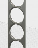
Wow, Fusion 360 was much easier for me to pick up on compared to SketchUp. Here's the drawing for a 1/4" aluminum baffle just wide enough to mount drivers to. I'm considering how this would interface with either the wall itself or some wings in a way that isolates it but maintains a tight seal. If I go this direction, then mounting from behind is an option again. I'm not super happy about the gap of drivers on top even though I realize the floor reflection is the one to prioritize. 26, 27, and 28 drivers is just really tough to deal with for a reasonable impedance. Maybe someone here has a combo that I haven't tried that ends up in the 4-10 ohm range?
Also, I sourced two pieces, 8' long, for $75 total. A little work with a 3" hole saw and a 1/4" round over bit and we're good to go!")
Also, I sourced two pieces, 8' long, for $75 total. A little work with a 3" hole saw and a 1/4" round over bit and we're good to go!
Attachments
Last edited:
You make it sound easy. I remember that particular job, it was anything but easy .
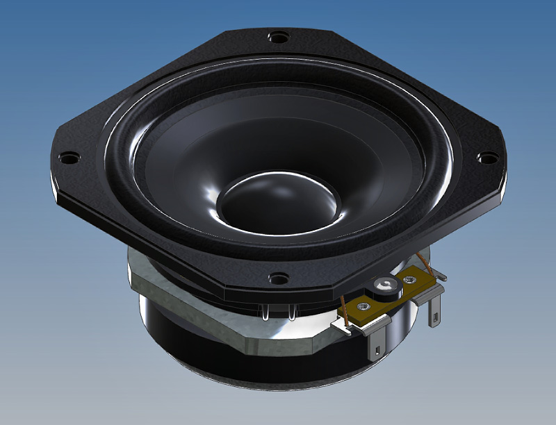
You can download my 3D Vifa model to check the fit...
.You can download my 3D Vifa model to check the fit...
I got a request in PM for the 3D model I made of the Vifa TC9 FD18-08. I've had similar requests before and made a "branded" version to share.
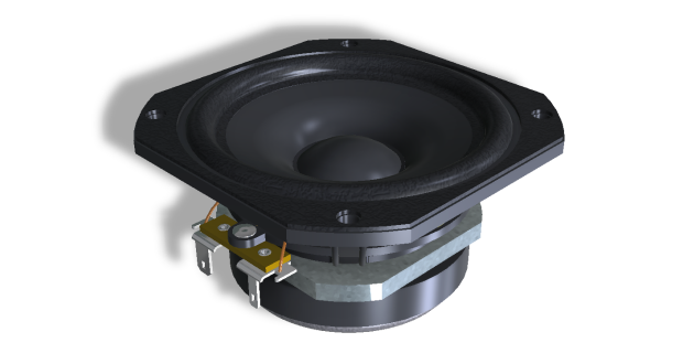
On the magnet and basket spokes it will read: Vandermill Audio
Hope you guys will keep that embossed in there and not just run away with my work
Here's the model: http://www.rsr-concepts.com/diyma/Vifa-Branded.zip
Oh awesome! Thanks! I know it won't be easy... a bit tongue in cheek on that one.
Also, I think I might be able to squeeze 28 drivers in there which grouped 4 x 7 gives me 4.57 ohms which my nCores can handle. Or 7x4 which gives 14 ohms but I think 4.57 is preferable, no?
Also, I think I might be able to squeeze 28 drivers in there which grouped 4 x 7 gives me 4.57 ohms which my nCores can handle. Or 7x4 which gives 14 ohms but I think 4.57 is preferable, no?
Last edited:
A win! I like it too.Wow, Fusion 360 was much easier for me to pick up on compared to SketchUp.
Here's the drawing for a 1/4" aluminum baffle just wide enough to mount drivers to. I'm considering how this would interface with either the wall itself or some wings in a way that isolates it but maintains a tight seal. If I go this direction, then mounting from behind is an option again. I'm not super happy about the gap of drivers on top even though I realize the floor reflection is the one to prioritize. 26, 27, and 28 drivers is just really tough to deal with for a reasonable impedance. Maybe someone here has a combo that I haven't tried that ends up in the 4-10 ohm range?
Also, I sourced two pieces, 8' long, for $75 total. A little work with a 3" hole saw and a 1/4" round over bit and we're good to go!
You will need a little more space at the bottom as you will probably need a bottom plate of some kind. That baffle is great as a cover plate but I would advise to build it in a sandwich like wesayso did. fix the drivers to the back panel fill the gap around the drivers with damping fix the cover plate to the top.
Even 1/4" aluminium with all the holes cut in it is going to have a bit of bend over 2m.
You can also mount the drivers to the baffle but just short them out, i.e. connect positive to negative on the driver and not connect them to the system. You get the look you want without having to mess with the impedance.
4.5 is better than the 14 for the Ncore if you want to use it's available power. The amp will prefer the 14 but you won't get anywhere near as much power out of it.
You make it sound easy. I remember that particular job, it was anything but easy
You can download my 3D Vifa model to check the fit...
Highly recommended!
I have the generation before the HDMI port showed up next to the SD card slot. Still have the optical drive too. My wife has the newer one though. So theoretically, I can use hers but she probably doesn't want it monopolized by my audio stuff. Thunderbolt to HDMI should work though. And as Perceval mentioned, DRC works with Wine, AU Lab, and Soundflower work so I'll give it a go with what I have before spending money. My computer skills are only so-so though and I may end up getting frustrated enough to just spring for the NUC or something similar.
DRC doesn't need to be run in real time on the same computer as it is just generating a filter file based on a measurement input. No problem to do that with WINE or any other method.
I have been down this road before and whilst I love my Macbook I wouldn't choose it as a media centre. I can appreciate that you are building a house so you are probably haemorrhaging money and don't want to spend anymore than you have to.
I think a NUC is the ideal device for this task, it has enough power to run the programs is quiet and comes in a nice aluminium chassis. They are small and can be hidden anywhere. They have most of the connections you need and they include an IR remote receiver. I really like to use a remote to control things when I am watching movies and TV to scroll through the library etc. There are other ways to achieve the same thing but there is nothing easier than sitting on the couch and using an IR remote to play, stop and scroll through your library. To me it is well worth the cost.
Now I'm done plugging the NUC!
Would the non connected drivers act like passive radiators to some degree? And is there any appreciable addition to the effective volume as a result? I did buy some extras in case of QC issues so I have them. Figure I might as well use them if I can though.
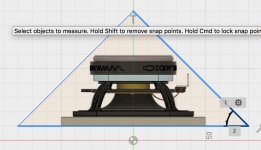
I can't figure out how to get wesayso's model into my baffle model? Fusion Help was not helpful.
I can't figure out how to get wesayso's model into my baffle model? Fusion Help was not helpful.
Would the non connected drivers act like passive radiators to some degree? And is there any appreciable addition to the effective volume as a result? I did buy some extras in case of QC issues so I have them. Figure I might as well use them if I can though.
I can't figure out how to get wesayso's model into my baffle model? Fusion Help was not helpful.
If you short them they would be braked, any effect should be very minor. You can also seal off that section. You would lose more volume that way but I don't think the volume is all that important if you are going to shove it right in the corner as volume will be limited anyway, an extra few CC's per driver isn't worth worrying about i.e. going from Q 1 to Q 0.98.
To me 25 is ideal as it is easy to wire them for 4 or 8 ohm and you have a balanced amount of series and parallel connections.
I was trying to help you get over your visual objection to the baffle you drew which I can understand, it's not balanced and therefore doesn't look quite right. Are you going to have it visible, no fabric?
You need to import the file this link will show you how.
https://knowledge.autodesk.com/support/fusion-360/troubleshooting/caas/sfdcarticles/sfdcarticles/How-to-import-or-open-a-file-in-Autodesk-Fusion-360.html
I got it into my data panel. And can open it by itself. I can't figure out how to get it next to my baffle though.
Right click on it in the data panel and choose insert into current design
(Assuming that your baffle is the current design)You can then move it around.
You can try and select the centre of the driver and move that to be at the same point as the centre of your opening, you may then need to change views to move it in or out.
I found the best way was to create the mounting holes in my driver cutout based on the datasheet and then select the centre of the mounting hole in wesyaso's model and move those points together.
Once you have one right you can then make it a component and pattern it down/up your line.
Thanks for the tips... I don't know why I didn't try right clicking. The pattern feature is pretty nice too. I can't believe I waited this long to learn a CAD program again! I was pretty decent at AutoCAD (2D) way back in the early 90's. And you would think that SketchUp would have stuck a little better. But Fusion is so much easier for me for some reason.
And wesayso... that model is incredible! Well done!
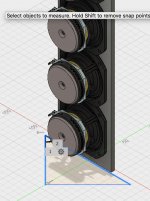
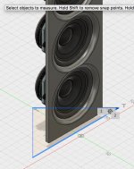
Looks like I need a front baffle of 160mm if the drivers are going to fit in the corner at all which is pretty close to what I had originally thought. But you can see how little room there is for the back wave. And actually, the magnet is more in the way than I had in my head mostly because I was using the Dayton ND driver with the tiny neodymium magnet for my previous mockups. But also, nothing was to scale previously.
I have the drivers mounted behind the baffle at the moment thinking that the 1/4" aluminum allows me to do the round overs without sacrificing too much strength between drivers. I really like the look. Downside is it steals more volume from enclosure and puts the back wave that much closer. I'm not sure it smooths out the response much? And there's a good chance I hide these behind grill cloth anyway so maybe the look doesn't matter much. Maybe I can pretty up the CAD sketch and convince my wife to show the baffle off.
Still pondering the whole building into the wall thing. Now that I'm trying out Fusion, maybe I'll lay those ideas out more precisely and that might help with the decision making.
And wesayso... that model is incredible! Well done!
Looks like I need a front baffle of 160mm if the drivers are going to fit in the corner at all which is pretty close to what I had originally thought. But you can see how little room there is for the back wave. And actually, the magnet is more in the way than I had in my head mostly because I was using the Dayton ND driver with the tiny neodymium magnet for my previous mockups. But also, nothing was to scale previously.
I have the drivers mounted behind the baffle at the moment thinking that the 1/4" aluminum allows me to do the round overs without sacrificing too much strength between drivers. I really like the look. Downside is it steals more volume from enclosure and puts the back wave that much closer. I'm not sure it smooths out the response much? And there's a good chance I hide these behind grill cloth anyway so maybe the look doesn't matter much. Maybe I can pretty up the CAD sketch and convince my wife to show the baffle off.
Still pondering the whole building into the wall thing. Now that I'm trying out Fusion, maybe I'll lay those ideas out more precisely and that might help with the decision making.
Attachments
- Status
- This old topic is closed. If you want to reopen this topic, contact a moderator using the "Report Post" button.
- Home
- Loudspeakers
- Full Range
- "Wall-integrated" corner loaded line array with Vifa TC9 drivers