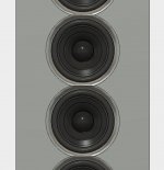
I put the walls in just to illustrate scale. I also tried to position holes for the screws that would attach to the walls. I think they're too far from the edge though. They look ok from the front though.
Next step is to try putting holes in the walls that would help with the back wave and also lead to the additional volume.


Next step is to try putting holes in the walls that would help with the back wave and also lead to the additional volume.
I put the walls in just to illustrate scale. I also tried to position holes for the screws that would attach to the walls. I think they're too far from the edge though. They look ok from the front though.
Next step is to try putting holes in the walls that would help with the back wave and also lead to the additional volume.
Good work with Fusion 360, it certainly helps to show just what any baffle arrangement and distances will look like.
To mount the aluminium you will probably need to use a triangular piece of wood. Screw the wood to the wall and the baffle to the wood with a layer of neoprene between both. Not easy to drill through aluminium on an angle like you had shown before. Possible but not easy, the number of holes and the size of the plate would make it that much harder too.
The primary issue with the backwave will come from the triangluar corner directly behind the driver this will end up being the shortest distance for the backwave to hit the cone. Cutting holes in the wall will not make this any better, only more distance or better absorption in damping will do that. That is the last time I will mention that too.
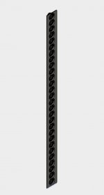
Sorry for the slew of images... I'm on a roll! These show 2" holes to one side of the drivers.
For the holes through Aluminum, I agree those should be square to the face. I will likely use those holes to drill pilot holes through the walls. And I was thinking the same on the neoprene or some other damping material. If I do pilot holes, I don't think I'll need the extra piece of wood.
On the back wave, I was thinking that behind the driver actually wouldn't be as bad given the size of the magnet. I agree that it's not ideal regardless since it's so close. I also only have those 2" holes on one side of the rear but I could do both sides I suppose. Just more work is all. And I disagree that they won't help. Would not some of the back wave energy get dissipated through those holes and the damping that will be on the other side of the holes? It's not ideal and I'm not sure how much it would help, but it's something.
On the back wave, I was thinking that behind the driver actually wouldn't be as bad given the size of the magnet. I agree that it's not ideal regardless since it's so close. I also only have those 2" holes on one side of the rear but I could do both sides I suppose. Just more work is all. And I disagree that they won't help. Would not some of the back wave energy get dissipated through those holes and the damping that will be on the other side of the holes? It's not ideal and I'm not sure how much it would help, but it's something.
The magnet will shield the back of the cone to some extent. It's not really the overall energy but discrete reflections arriving off reflective surfaces and not being fully absorbed in the damping that causes the problems. Remember also you have many drivers in a line producing the same program so the reflection may come from the back of one and pass through the cone of another. I've tried to give as much information and reasoning for my position as I can. If you disagree and are sure you understand the acoustics go for it, you are the one building it.
I have my own build to get on with so the proof of the pudding will be in the measuring and listening
")
If you are willing to cut holes in the wall behind the baffle, you should be willing to remove the drywall behind them too? The more open right behind the driver the better.
I've given you all the pointers I can think of. The impedance tests, detail being important if you have the same situation for 25 drivers etc. I do hope you plan on using more than that single alu baffle to hold the drivers. It will need damping and there's a good reason I used a double baffle, one 10 mm and one 6 mm with butyl between them. I'd advise to re-read all pointers and come up with your own smart solution.
One more time: make a test box with a single driver (doesn't need to be on the real wall, just fake/imitate the corner with scrap material) and test/measure it.
Glad you're having fun with that model. It's pretty accurate.
Last edited:
Thanks for the guidance. I will need to figure out what I want to test when we actually get back in our house. And removing the drywall is an option. I though that would help deaden the rear walls though.
Did you test a single 6mm baffle? Certainly, yours is better. But I'm curious how much better?
Did you test a single 6mm baffle? Certainly, yours is better. But I'm curious how much better?
Use Science to design your speakers and they will sound like a piece of Art... except when you can just over-engineer the crap out of it in which case it's fine.
I'm more of a value guy both in terms of both money and effort... in case it wasn't already clear. Over-engineering is fun too when it doesn't cost me much.
Anyone tryout the simulations in Fusion? I wonder if it can tell you about resonances and such. At least directionally, it could help you decide where on the spectrum of over-engineered you want to be.
Are commercial vinyl tiles similar to mass loaded vinyl? Seems like they might be easier to cut than the vinyl. And perhaps cheaper too. But unclear if the damping properties are worse? I was also thinking bout whether there are other options that are silicone or urethane based that might be more dampening?
Are commercial vinyl tiles similar to mass loaded vinyl? Seems like they might be easier to cut than the vinyl. And perhaps cheaper too. But unclear if the damping properties are worse? I was also thinking bout whether there are other options that are silicone or urethane based that might be more dampening?
No they are much lighter, they don't have the mass. The mass is provided by impregnating minerals of different kinds to increase the weight and density.
Look at car dampening / sound isolating products, they usually come with a foil side and an adhesive side. There are others that have MLV attached to a layer of foam. They are heavy so the shipping can be expensive but the product can be bought fairly cheaply if you can pick it up locally.
Things similar to Dynamat, Silent Coat or many other trade names.
These give you dampening by providing mass without stiffness which is good for damping the baffle and will provide some isolation if you use it between layers.
To isolate the baffle from other objects neoprene or similar will do a better job.
Are you isolating the drivers themselves from the baffles too? I was thinking either the MVL or similar between the drivers and baffle. And then something to isolate the drivers from the screws like the post in the other thread via oring or similar. Then isolating the baffle from the wall in a similar fashion. i.e. with neoprene between baffle and walls and again, some oring between the screws and the baffle.
Are you isolating the drivers themselves from the baffles too? I was thinking either the MVL or similar between the drivers and baffle. And then something to isolate the drivers from the screws like the post in the other thread via oring or similar. Then isolating the baffle from the wall in a similar fashion. i.e. with neoprene between baffle and walls and again, some oring between the screws and the baffle.
Not really in my build. I have a layer of foam weather stripping as a gasket in the driver recess, this is mainly for an air seal. It will provide some cushioning as it is not completely squashed, it is compressed to about 1mm.
I could use O rings in the mounting screw recesses to isolate the cabinet from the driver more. They are quite expensive and I would need a lot of them and I have some concern over how the screws will hold in the mdf if there is not firm contact between the screw head and the basket. If I was using ply or tapped bolts then the last point would not be a concern.
It is always something I can retrofit if the impedance measurement suggests it is needed.
You could do it like that, remember that the MLV is better at damping and the neoprene is better at isolating. The neoprene is squishy and lossy. The MLV is solid and heavy.
MLV is often used as a sound barrier. In cars it's often used with neoprene underneath to block (outside) sound.
Neoprene (and maybe even better, sorbothane) is used as an isolator.
Butyl damping mats with alu foil as a (CLD) damping material.
I used MLV on my baffle to weigh them down, make them heavier. It's not a flexible material and it doesn't work as a CLD layer between two stiff materials. Butyl would be way better at that. I've tried MLV and neoprene between both baffles I use. I stripped it all out again and replaced it with butyl rope to gain damping. A measurable improvement.
Look at MLV as being effective as a sound barrier. Or a means to add weight. If you compress it, it won't return to its original shape. It works even better if isolated (for instance with neoprene) from the "wall" it's used on.
Looks like I can get 3" inside diameter rubber o-rings. 3/32" thickness would be a nice way to separate the drivers from the baffle. Just need to make sure they won't interfere too much with the mounting holes. Similar material for the four screws per driver would further isolate. It's a lot of o-rings but this reduces the demand on baffle isolation. I would do MVL for the rest of the baffle too. Perhaps isolated using a urethane adhesive. And then I can use sorbothane strips to seal and damp at the interface of the baffle and the wall.
That seem like the right mix of materials for the right uses?
That seem like the right mix of materials for the right uses?
Last edited:
To give an example of the MLV I use:
Bestel Isomat TS geluidsisolatiematten direct online op Akoestiekwinkel.nl!
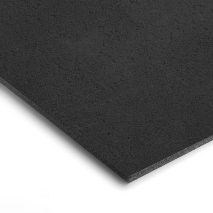
The 3.2 mm thick Mass Loaded Vinyl weighs 8 Kg per square meter (!)
The thicker 5.7 mm weighs 14 Kg per square meter (!)
Mostly used as a sound barrier, with excellent results. Look at this pfd file to see some graphs (sorry it's in Dutch)
http://www.merford.com/media/202645/isomat-ts.pdf
I use it in my car on the back of my door card to block sound as it's the enclosure for my mids.
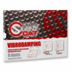
The CLD damping I use is 4mm thick Silent Coat:
https://www.caraudioshop.nl/silent-coat-extra-shop-pack

This consists of mostly butyl with an aluminium foil layer as the sheer layer. This is the stuff comparable to Dynamat etc.
Bestel Isomat TS geluidsisolatiematten direct online op Akoestiekwinkel.nl!
The 3.2 mm thick Mass Loaded Vinyl weighs 8 Kg per square meter (!)
The thicker 5.7 mm weighs 14 Kg per square meter (!)
Mostly used as a sound barrier, with excellent results. Look at this pfd file to see some graphs (sorry it's in Dutch)
http://www.merford.com/media/202645/isomat-ts.pdf
I use it in my car on the back of my door card to block sound as it's the enclosure for my mids.
The CLD damping I use is 4mm thick Silent Coat:
https://www.caraudioshop.nl/silent-coat-extra-shop-pack
This consists of mostly butyl with an aluminium foil layer as the sheer layer. This is the stuff comparable to Dynamat etc.
Attachments

wesayso and fluid - do you have a recommendation for the size of screws for the drivers themselves? I'll likely be screwing them in from behind but I don't think that makes a difference. Simple pan head phillips? What size? (I'm thinking #6-32 in imperial.) I was thinking about the smallest reasonable size to allow for some play if need be. But not be too hard to drill and tap for.
Last edited:
wesayso and fluid - do you have a recommendation for the size of screws for the drivers themselves? I'll likely be screwing them in from behind but I don't think that makes a difference. Simple pan head phillips? What size? (I'm thinking #6-32 in imperial.) I was thinking about the smallest reasonable size to allow for some play if need be. But not be too hard to drill and tap for.
I am assuming that you are just going to use a single panel 1/4" thick, if not then the following may not be of much use.
I would not try to mount them from behind and drill and tap blind holes for small screws in 1/4" material. If you were to have it done professionally by a proper tap machine then that is a different story. Tapping small holes by hand in aluminium has a few downsides in this application. The first few threads tend to be wobbly and don't have much holding power you would probably need to have a 5mm depth which is very close to your thickness, blind taps don't have the clearing point so are harder to use by hand and tend to break.
I have tapped a lot of M3 holes in heatsinks for amplifiers and you need a good thickness for the thread to hold well if it has been tapped by hand. I have had some cases tapped by machine recently and the screws would hold in them with only 3mm of thread.
What I would do is drill through the panel and use socket head cap screws. I would counterbore the mounting hole on the front side to the depth of the socket head, that way you can use standard washers and nuts on the back to hold it all together. By doing this you can put a rubber grommet in the hole and the socket cap will fit the grommet better.
If you aren't going to use a grommet then you could use countersunk types. I prefer the ones that have a hex/allen head rather than phillips as they are easier to torque down without stripping the head.
But I find a counterbore easier to drill properly in metal, countersinks can chatter and are hard to get to the exact same depth.
I would go with M3.5 or #6, you can go as low as M3 or as high as M4 but they are a bit tight. An #8 size wood screw will not fit through.
That is a much better idea! It's not as clean looking on the front but the trade off is well worth it. Besides, I'd probably mess up enough holes where I would need to do this in those holes anyway and then I'd have a pock marked baffle.
Think I need additional washers on the nut side if I use silicone o rings to isolate the driver from the bolt? And do yo think counterbore is necesssary? An M3 button head socket is pretty small.
Think I need additional washers on the nut side if I use silicone o rings to isolate the driver from the bolt? And do yo think counterbore is necesssary? An M3 button head socket is pretty small.
- Status
- This old topic is closed. If you want to reopen this topic, contact a moderator using the "Report Post" button.
- Home
- Loudspeakers
- Full Range
- "Wall-integrated" corner loaded line array with Vifa TC9 drivers