2. No idea what you're getting at.
Sorry, that wasn't clear at all. I was referring to the general standard filters tab that has check boxes for psycho acoustic, minimal, soft, etc. I guess you just generate them all and then measure/listen to each of them separately to decide what you like?
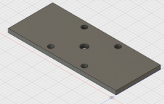
Drilling jig model. 1/2" aluminum to match drill bushings, 8" wide to match the baffle width. May also include holes for the mounting screws. But those do not require precision so I may just do those without the drill bushings. Width matches the width of the drivers so I can mark the spacing and position the jig appropriately before clamping.
Note: the holes are sized to accept the drill bushing outside diameter. The center one will hold a bushing for a 1/4" drill, the others for a 5mm drill.
Note: the holes are sized to accept the drill bushing outside diameter. The center one will hold a bushing for a 1/4" drill, the others for a 5mm drill.
Attachments
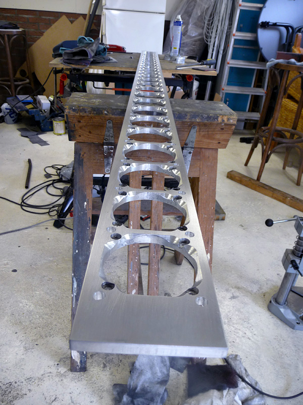
I'd add way more into such a template. I opted to include the holes for the baffle bolts spanning 3 drivers, to be able to do a number of things with them. If you take care and use a drill press or similar the bushings won't even be needed. Just use plenty of WD40.
Include a ~3" hole to be able to do your roundover with a bearing bit following the template.
I had 3 different sized holes in mine, one for the driver opening, one for my roundover router bit to follow and one for the holes in the back baffle. Plus 8 mounting holes for the baffle and I later drilled the tiny holes for the drivers themselves (I figured they might be too small for water jet cutting).


(as you can see I replaced the bearings with a fixed pin, the bearings exploded too often )
)

This simple though effective template was also used to drill all mounting holes.
(in one baffle, which then was used to drill the holes in it's partnering baffle)
I also made my own template to do the chamfering on the back of the baffle this way:


Only a slight deliberate change from the original plan. The straight edge between the drivers.
Include a ~3" hole to be able to do your roundover with a bearing bit following the template.
I had 3 different sized holes in mine, one for the driver opening, one for my roundover router bit to follow and one for the holes in the back baffle. Plus 8 mounting holes for the baffle and I later drilled the tiny holes for the drivers themselves (I figured they might be too small for water jet cutting).
(as you can see I replaced the bearings with a fixed pin, the bearings exploded too often
)
This simple though effective template was also used to drill all mounting holes.
(in one baffle, which then was used to drill the holes in it's partnering baffle)
I also made my own template to do the chamfering on the back of the baffle this way:
Only a slight deliberate change from the original plan. The straight edge between the drivers.
Last edited:
What is going on with the red/orange L-bracket? Is that a platform for your router? I didn't see the router behind it though so what is that bit attached to?
Also, did you route out all the holes vs doing a hole saw?
I was going to make the holes in one baffle as the router bit guide for the round overs in the other baffle. I've never seen bearings blow up like that and didn't know you could replace with a pin. Is that a standard part or did you have to engineer that yourself?
The bits I used were meant to cut wood, not aluminium. With WD40 cooling they did a wondrous job, except for the bearings.
They got heated too much, even when I got a transformer to reduce my (static) RPM's. My router does 18000 RPM standard.
The pin thing is the best I came up with, it worked very well.
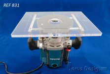
The L shaped bracket's task is to hold the pin where the router bearing used to sit. I'ts just a pin in the right diameter I needed (salvaged from an old chair). I've even used wrench sockets for a temporary right sized pin.
The router hangs upside down under the table, only the router bit sticks out here.
I didn't use a hole saw, just a jig saw and I used the router to get the holes to size with the templates. Very repeatable and exactly to size.

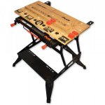
Here's a clear view of the table showing another router bit. The Router itself is bolted to the table at the back using it's side guide system. You can see the bolts that hold it. The table consists of a workmate and clamps the router, with a piece of multiplex as the table top.
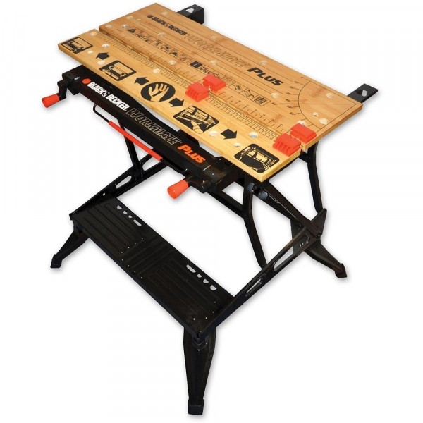
The router is clamped in this table while being bolted down to the multiplex. Instant router table!
Mounting looks a lot like this (using the side guide system that came with the router and a few pieces of wood):
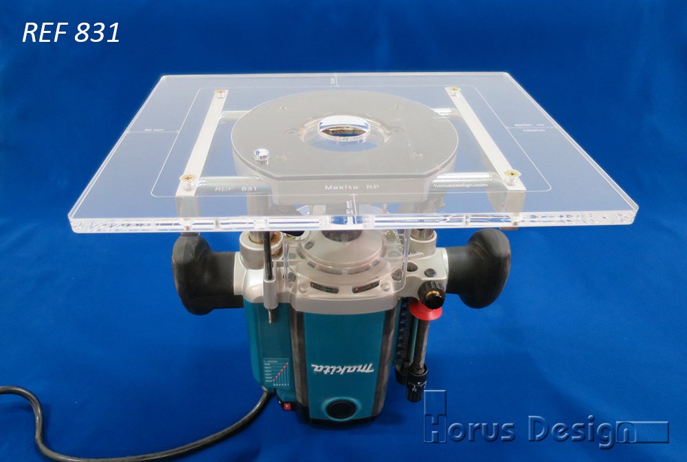
That orange piece as you call it is just some scrap L-iron I had laying around mounted on the remainders of the jig sawed holes scrap pieces (used as spacers) to be able to mount a pin exactly above the router bit. I welded on the "L" shape to keep it stable in all directions.
Use what you have is my motto.
They got heated too much, even when I got a transformer to reduce my (static) RPM's. My router does 18000 RPM standard.
The pin thing is the best I came up with, it worked very well.
The L shaped bracket's task is to hold the pin where the router bearing used to sit. I'ts just a pin in the right diameter I needed (salvaged from an old chair). I've even used wrench sockets for a temporary right sized pin
.The router hangs upside down under the table, only the router bit sticks out here.
I didn't use a hole saw, just a jig saw and I used the router to get the holes to size with the templates. Very repeatable and exactly to size.
Here's a clear view of the table showing another router bit. The Router itself is bolted to the table at the back using it's side guide system. You can see the bolts that hold it. The table consists of a workmate and clamps the router, with a piece of multiplex as the table top.
The router is clamped in this table while being bolted down to the multiplex. Instant router table!
Mounting looks a lot like this (using the side guide system that came with the router and a few pieces of wood):
That orange piece as you call it is just some scrap L-iron I had laying around mounted on the remainders of the jig sawed holes scrap pieces (used as spacers) to be able to mount a pin exactly above the router bit. I welded on the "L" shape to keep it stable in all directions.
Use what you have is my motto.
Attachments
Last edited:
2) I never bumped into any limit of usable PEQ slots. I used to use the first bank to do Pré EQ, have convolution setup between the two banks and used the second bank to do my edits after the convolution. (lowering energy at a dip on the low left frequencies and adding to the right to compensate. Some tonal balance tweaks etc.)
I have since moved the pré EQ to a separate plugin. I'm now using the first bank to separate my stereo signal to multiple channels for ambient and anti cross talk stuff. Keeps it organised.
When you did edits after convolution with the second bank, did you use REW to generate those filters too? Or was that more by listening? And would you not be able to get the same result by just tweaking the first set of PEQ slots?
3. I grew into a room target over time. Though I do have mid/side EQ making it harder to state what I have. The mid (or phantom centre) signal follows a normal target. The side signal is adjusted. It's complicated to explain (lol). The room target I ended up with pretty much matched preferred targets in literature.
This story by Mitch might help: Computer Audiophile - Dynaudio Focus 600 XD Loudspeaker Review
Looks like you ended up pretty close to what DRC defines as B&K and is also in that article. (Interesting read, thanks for the link.) I suppose it's easy enough to swap between the options and then you can measure and listen your way into a favorite much like the filter types in the standard filter tab.
Ah, I see now. That's a clever setup. Was the hole saw approach not precise enough for you? Or was it just a matter of being comfortable with this technique since you needed to use three different 76-ish sized holes?
It's that last answer. I needed 3 different sized holes to accomplish what I wanted. I used what I had on hand, having more time than money at that point in my life.
When you did edits after convolution with the second bank, did you use REW to generate those filters too? Or was that more by listening? And would you not be able to get the same result by just tweaking the first set of PEQ slots?
REW's auto EQ wasn't precise enough for me at this point. I used the IR and waterfall plots and a visual of the DRC correction to guide me though that step.
The reason to use both banks is simple. To be able to measure each step. This way I can verify each step along the way.
Looks like you ended up pretty close to what DRC defines as B&K and is also in that article. (Interesting read, thanks for the link.) I suppose it's easy enough to swap between the options and then you can measure and listen your way into a favorite much like the filter types in the standard filter tab.
I tried many house curves in separate sessions, though I ended up really close to a curve over time, not trying to hit a specific target. In all fairness this would be the target of the phantom centre. My sides are EQ-ed slightly different.
Another disclaimer, I don't use DRC's standard templates, I also don't use their targets. Both are custom to get what I want. Lots of measuring sessions and even virtual sessions to learn what each parameter does in DRC were done to create my own preference template and curve.
It's all in that huge thread of mine though. I even shared my template at one point, buried in that thread. It isn't the latest version but close enough for a start. I'm always looking for ways to get better results. Details do matter.
It's clear to me you didn't read my entire thread. I can't blame you, it's huge. But a lot of your questions would be answered right there. I don't mind giving answers to questions, but if you want to know the "why's" a read would help.
I can tell you what I did, but if you understand why I did it, all of it will start to make more sense. (or not, I might be crazy, who knows
)You won't believe what I've tried and not written down. I engaged this as a study, trying to make sense of it all. It's linked to a lot of theory that I wanted to try out for myself. If what I've written seems like a lot, I've read at least 20 times more papers and pieces and posts to come up with the ideas and inspiration for my experiments etc. In this forum I know I'm not the only one "possessed". But keep in mind my goals may have been different from what you want to achieve.
Another good thread (and a lot smaller than the Towers thread) is the one about convolution.
Might help you, 1+2, to get some info about DRC:
http://www.diyaudio.com/forums/full...ectrical-loudspeaker-correction-networks.html
Might help you, 1+2, to get some info about DRC:
http://www.diyaudio.com/forums/full...ectrical-loudspeaker-correction-networks.html
That dimension with a 1/4" baffle will give you this.
View attachment 599169
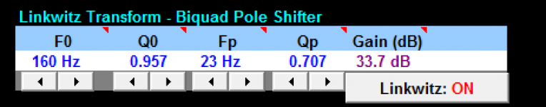
I think that is enough to allow you to get down to between 20 to 40Hz with EQ but you lose a bit of output volume potential. You have a couple of pretty big subs so you should be able to get that back by relaxing the eq when the subs are on. I'll run a sim in Jeff bagby's woofer designer as that has a linkwitz transform simulator. Room gain and corner loading won't be included though so it isn't a complete picture.
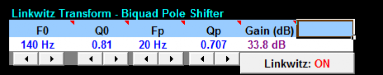
I said I would do this and didn't have time until now. Woofer designer did not work well with the TC9 the volume and Q came out all wrong but the Linkwitz transform prediction is still valid as a relative measure between the enclosures.
I entered the F3 and Q numbers from Bassboxx to show the difference.
With a bigger enclosure ~2L F3 is 140 and to equalize that to 20Hz means you lose almost 34dB in maximum output from the EQ.
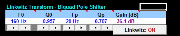
With your proposed size F3 is 160 and getting to 20Hz takes a 36dB loss so overall you lose a little more than 2dB of output potential by going with the smaller cabinet, so it will take almost twice as much power to get back to the same level. The driver won't take that power however before reaching it's thermal limit.
The maximum output will be different for the array due to the extra drivers and boundary loading so the dB figure is only useful in a relative sense.
EQing to 23Hz gets a very similar figure
So you could EQ to almost the same target but you couldn't turn it up as loud without reaching the thermal limit due to the way the smaller box loads the drivers. You burn more amp power in the drivers as the cabinet is less efficient.
Attachments
Thanks fluid! 2dB is actually less than I thought the difference would be. Given the corner loading gain of 6, 9, or 12dB depending on which theory you prescribe to, I feel pretty good about the trade off. And of course, I plan on having subwoofers so relaxing the EQ is certainly in the cards for movies at least.
Thanks fluid! 2dB is actually less than I thought the difference would be. Given the corner loading gain of 6, 9, or 12dB depending on which theory you prescribe to, I feel pretty good about the trade off. And of course, I plan on having subwoofers so relaxing the EQ is certainly in the cards for movies at least.
2dB in this context is actually quite a lot, it is the difference between 10W and 16W, or 30W and 48W, multiply that by 25 and it is a lot more power.
The 2L chamber takes 18 watts to reach x-max, a 2dB increase on that is about 29W, but in the small chamber it takes 41W to reach x-max. 18x25 =450W, 41x25 = 1025W, that is a 3.7dB difference and more than enough to toast your drivers!
What this means is that the bigger box is excursion limited but the smaller box is thermally limited.
None of this is to put you off or to suggest you are doing the wrong thing just to be aware that it would be possible to thermally cook the drivers in that small cabinet long before they got anywhere near their excursion limit. The other thing to bear in mind is that the burnt power ends up as heat in the magnet and with less air volume there is less cooling. More heat will mean more non linearity in the long term.
Basically go easy on the EQ until you have it properly tested. You might not be able to tell with a short listen that the drivers are being stressed because the excursion and therefore distortion would still be fairly low but the heat will build up over time.
All of these figures are really only valid from 200Hz and up so the corner gain will help to bring the bass up to the same level but won't eliminate this as an issue.
Something to think about in any case and a good reason to employ the subs
How should I be thinking about the SPL here though? I see what you're saying and agree with the tradeoffs in x-max vs thermal limits. But is this extreme case relevant at sane listening levels? Even if dynamic range comes into play to have headroom to create those big spikes in movies for example, being spikes, thermal limits wouldn't come into play either as the high volume levels will not be sustained over time.
Again, probably all academic since I will have subs. But just curious on whether my thinking is sound.
Again, probably all academic since I will have subs. But just curious on whether my thinking is sound.
But is this extreme case relevant at sane listening levels?
Whether this represents an "extreme" case will depend on how loud you like to listen. What I can tell you is that a good speaker with low distortion does not sound loud so you tend to keep turning up the volume because it sounds good and you can tolerate the volume.
If you have a umik or spl meter then it would probably be helpful to you to know how loud you are currently listening to music so you can reference a known level for what you consider to be loud, normal or extreme.
To apply a few numbers to try and bring it into perspective, 90dB plus is most peoples comfortable loud listening.
106dB might be the maximum reasonable output that the line can put out without EQ, add in 15 to 20 dB of EQ towards the bottom end and now you reduce that to 86 to 90dB, but the power being put in hasn't reduced as it has been sucked up by the EQ. This is where the power comparison come into play the more you EQ the small cabinet the worse it gets.
All correct but depends on the base load you are putting in to get your average spl above.Even if dynamic range comes into play to have headroom to create those big spikes in movies for example, being spikes, thermal limits wouldn't come into play either as the high volume levels will not be sustained over time.
Again, probably all academic since I will have subs. But just curious on whether my thinking is sound.
I mention this because you had suggested earlier on that you were drawn to the idea of music over the lines without subs due to some of the positive comments. Add in subs below 80Hz and most of this disappears completely as an issue. But if you were to try and emulate something like wesayso's EQ you could quickly start to get towards the danger zone with your smaller cabinet volume if you have the amp power available.
Wesayaso only has a 100w amp so there is an inbuilt limiter right there. Your ncores which can give 200w at 8ohms would still be safe. The hypex clips fairly hard at that point though and your cabinet is likely to use most of that power to get the same output level wesayso's would at 100w.
Another reason to use the subs
All good points, thanks. I may go ahead and build the volume into the walls anyway. It seems like I might as well if I can. It makes things a little more complicated. Since I can pretty much make the volume whatever I want, what is the volume for a Q of 0.707? I think one of your bassboxx sims had a Vb of 1.991L for a Q of 0.798. Is that accepted universally as the best target for flat response and high SPL? And are there tradeoffs for going lower to 0.577 for better damping and transients?
Question about the interface from the baffle to the wall. Since the idea is to isolate the baffle from the wall, wouldn't it be better to let the corner rest against the neoprene? Would that not reduce the amount of energy transferred to the walls compared to making a bevel and having the resulting face against the neoprene? I can see tradeoffs in both ways.
All good points, thanks. I may go ahead and build the volume into the walls anyway. It seems like I might as well if I can. It makes things a little more complicated. Since I can pretty much make the volume whatever I want, what is the volume for a Q of 0.707? I think one of your bassboxx sims had a Vb of 1.991L for a Q of 0.798. Is that accepted universally as the best target for flat response and high SPL? And are there tradeoffs for going lower to 0.577 for better damping and transients?
The TC9 has a very high Qt at 0.89 which means that it takes a very big box to get to a Q of 0.7, 10 litres per driver in fact. This is too much as puts very little loading on the cone. This is the wrong driver to get a low Q response from.
Generally 2 x Vas is about as big you would want to go. Vas is 1.24L so 2.5L per driver is about as much as you need maximum. This is the reason most settle somewhere around 2L as it is really the sweet spot with this driver.
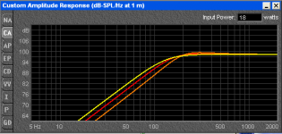
This shows the difference between 10 litres Q 0.7 in Yellow, Red is ~2L at Q 0.8 and Orange is Q 0.957.
The cabinet Q sets the rolloff shape which can be changed to whatever you want with EQ, bearing in mind the more EQ, and the more it resembles a Q=0.5 type rolloff the more headroom you lose as before.
Attachments
Ah, I see. I didn't realize that it would be so exponential. I'll target for somewhere around 2L. Exact volume will likely depend on construct-ability. I assume it's ok if the left and right are slightly different since I'll EQ separately? Plus, maybe I'll end up like wesayso with slightly different curves left and right. Unlikely to be very much since my room is pretty symmetrical. But separating them can't hurt, right?
Last edited:
- Status
- This old topic is closed. If you want to reopen this topic, contact a moderator using the "Report Post" button.
- Home
- Loudspeakers
- Full Range
- "Wall-integrated" corner loaded line array with Vifa TC9 drivers