Ah, I see. I didn't realize that it would be so exponential. I'll target for somewhere around 2L. Exact volume will likely depend on construct-ability. I assume it's ok if the left and right are slightly different since I'll EQ separately?
There will be some differences in the driver parameters anyway so an exact match isn't required but I would try and keep it as similar as you can.
Plus, maybe I'll end up like wesayso with slightly different curves left and right. Unlikely to be very much since my room is pretty symmetrical.
I think the symmetry will mean that your EQ should be very similar as any reflection or room induced issues should be common to both.
No idea what this means.But separating them can't hurt, right?
There will be some differences in the driver parameters anyway so an exact match isn't required but I would try and keep it as similar as you can.
I think the symmetry will mean that your EQ should be very similar as any reflection or room induced issues should be common to both.
No idea what this means.
I meant separating the EQ for left and right.
Haha, yes. FIR too. I guess technically FIR does not fall into the umbrella of EQ. But that's how I meant it.
The EQ will always be applied separately to the left and right channels but you might choose to use the same filters on both. That would depend on the method of equalisation.
EQ can be to either alter frequency or phase independently, or more normally both at the same time. Anything that is a filter and not a pure delay could be considered to be EQ.
An FIR "Finite Impulse Response" filter is a more sophisticated method of equalisation as it has the ability to change the phase response independently of the frequency response.
Maybe I am just being pedantic now
")
Huh? The 0.89 was measured in an IB, right? Can't a box only raise the Qts from that point?The TC9 has a very high Qt at 0.89 which means that it takes a very big box to get to a Q of 0.7, 10 litres per driver in fact.
The 0.89 is the Manufacturers spec and I would think was measured on an IEC baffle, (big, not infinite) but it isn't specified in the datasheet.Huh? The 0.89 was measured in an IB, right?
I don't think that the manufacturers spec can be considered the same as a true infinite baffle which is the only way what you say there would be true.Can't a box only raise the Qts from that point?
If that Q resulted from an infinitely large enclosure then obviously you can't then increase the box volume to lower the Q. I would think that the Vas would be huge too which it is not.
All the modelling of this and similar drivers together with actual measurements of enclosures show that fairly small enclosures (2L) can lower the Q from the manufacturers spec.
Help file for WinSpeakerz claim The net Q of a closed box can never be less than the driver's Q(ts) although its possible to ask for Q(tc) set as say 0.707 for TC9 driver result is box volume goes negative.
Seems make sense when not long ago had high Q(ts) TC9 on same ~160x120cm OB verse low Q(ts) 10F.
Seems make sense when not long ago had high Q(ts) TC9 on same ~160x120cm OB verse low Q(ts) 10F.
Attachments
Help file for WinSpeakerz claim The net Q of a closed box can never be less than the driver's Q(ts) although its possible to ask for Q(tc) set as say 0.707 for TC9 driver result is box volume goes negative.
Seems make sense when not long ago had high Q(ts) TC9 on same ~160x120cm OB verse low Q(ts) 10F.
Byrtt,
I think I have a reason as to why all of this can be correct even though it might seem contradictory.
Qts of a driver is the total value of Q (mechanical and electrical) at the resonant frequency. When you put it in a box the effective resonant frequency of the driver changes and therefore the Qts of the driver at that resonant frequency will be different.
To illustrate that the actual Q of the combined cabinet and driver can be less than the manufacturers spec, and to prove it to myself see below.
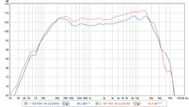
I have done some calculations based on a chart wesayso posted of his impedance.
I put this into CAD so I could draw some lines to find a fairly accurate figure for the frequencies and impedances I need. If the original file was still available in REW then more accurate figures could be obtained.

This shows how to calculate the Q of the driver and enclosure together from the impedance measurement.
http://www.linkwitzlab.com/images/graphics/f0Q0.gif
From the drawing I have
Rmax =11.73
Rdc = 6.32
sqrt of rmax x rdc =8.61
gives
F1 = 110.56
F2 = 265.38
F0 = 171.29
Put those numbers into the Q calculation and it comes out with a Q 0.77.
This agrees completely with the figure bassboxx gives for a heavily damped chamber with an effective volume of 2.6L.

Maybe I am wrong but to me this all makes sense and allows for all of the above comments to be correct when viewed from the correct point of view
Maybe I am wrong but to me this all makes sense and allows for all of the above comments to be correct when viewed from the correct point of view
Good points and nice piece of work
Anybody interested in a group buy of the ultimate Vifa/Peerless/Thympany driver TG9FD10-08 .
Price around $6 but there has to be many interested as minimum number of drivers for that price is >2000 pcs.
Interested thanks
2000 pcs that is about fourty new stereo sets or twelve AV sets
If I can't quite squeeze 28 drivers in, can I use 27 drivers and an 8 Ohm resistor? That means one of the series sets wouldn't be exactly the same as the others, but would it be close enough?
Worst case, I can go to 25 drivers or do 27 drivers with the top and bottom shorted as fluid had suggested. But I like the idea of a 4 Ohm impedance and of course, truly making this as close to floor to ceiling as possible.
I haven't given up on 28 yet, but it's going to be close. Close enough that I want to wait and see how much hardwood floor they sand away before making a decision!
No problem at all with the 8 Ohm resistor. The efficiency you lose would be VERY small.If I can't quite squeeze 28 drivers in, can I use 27 drivers and an 8 Ohm resistor? That means one of the series sets wouldn't be exactly the same as the others, but would it be close enough?
Worst case, I can go to 25 drivers or do 27 drivers with the top and bottom shorted as fluid had suggested. But I like the idea of a 4 Ohm impedance and of course, truly making this as close to floor to ceiling as possible.
I haven't given up on 28 yet, but it's going to be close. Close enough that I want to wait and see how much hardwood floor they sand away before making a decision!
Yes you can, Roger Russell has a small section in his article that describes what he would do.

If you use a power resistor you might want to attach it to a small heatsink or directly to your aluminium baffle to act as a heatsink. The power rating is not always given in free air.
If you are going for ~4 Ohm then 28 drivers makes sense even if one is actually an 8 ohm resistor.

If you use a power resistor you might want to attach it to a small heatsink or directly to your aluminium baffle to act as a heatsink. The power rating is not always given in free air.
If you are going for ~4 Ohm then 28 drivers makes sense even if one is actually an 8 ohm resistor.
If I can't quite squeeze 28 drivers in...
CC for the TC9 is 84mm, 28pcs = 235.2mm array height.
If you trim off 1mm on top/bottom flange (Modificed CC 82mm) you are down to 229.6mm.
I considered this myself for v2 (which wont happen soon)
The frame doent have too much excess material but I will glue my TC9 next time around. Using a trim router/table should make the trimming a quick affair.
Excellent... I got a couple 100W wire wound aluminum cased ones for just a few bucks. Good idea to mount to the aluminum baffle although I'm not worried about the power rating obviously.
The power rating is a little misleading as they are usually not in free air. i.e. they are rated to 100w but only if attached to a heatsink that can dissipate that power. Your aluminium baffle should be sufficient for any reasonable amount of power you might put in so it is a little academic.
Somewhat irrelevant extra information:
This is where a spec can be true but not in the way you want it to be. Just think how hot that amount of aluminium would get if you were to dissipate 100w of power through it. They might be OK for a minute or two but once the heat builds up over time maybe not so much. Surface area is what dissipates heat. Just think of the size of the heatsink you would have for a 100w amplifier.
Surface area is what dissipates heat. Just think of the size of the heatsink you would have for a 100w amplifier.
I have a classA 50W stereo amp (2x25W), it gets nice and toasty despite heatsinks are 14x8x2" per channel
- Status
- This old topic is closed. If you want to reopen this topic, contact a moderator using the "Report Post" button.
- Home
- Loudspeakers
- Full Range
- "Wall-integrated" corner loaded line array with Vifa TC9 drivers