1. Minimum footprint/aesthetic impact: Try to make these visually disappear into the room as much as possible. Translation - what's a reasonable minimum volume per driver for the FR to go low enough to cross over to the subs while considering reasonable boost due to both corner loading as well as EQ. Although a QTc of .707 seems to be a common target, my thought is that I can probably get away with something closer to 1.0 with the aforementioned boosts and still have a reasonable rolloff to the subwoofers. Does that seem reasonable? I know that a larger volume has benefits, but given the goal here, it seems this is a workable compromise. (I realize I haven't talked about the subwoofers themselves, but for context, they are 2 18" stereo integrity units that will be driven by an iNuke 3000.)
First you need to decide just how important the aesthetic is to you and what are you prepared to sacrifice to get it.
2. Sound cabinet design: Independent of the volume that gets me to a QTc around 1.0, there are considerations to make sure that the cabinet design supports a high quality result.
Issue 1: The enclosure should be able to deal with potential back wave issues per fluid's comment in post 164. That may mean a larger enclosure or some other way of deflecting the back wave. I'm not sure if the triangular shape helps or hurts this. On one hand, the rear is closer to the driver than with a traditional design. On the other hand, the rear is angled so the wave would be reflected back at an angle although I suppose they would sum on the way back anyway? Another thought is to use a 1" diameter cylindrical dowel between braces at the rear (near the 90 degree vertex) so that could further scatter the back wave? I'm unclear as to how to predict this other than building a test enclosure. So I may do that once the general design parameters are decided upon. But I would lean towards being aggressive on this given the distribution of energy across so many drivers means each driver won't need to work that hard and so the back wave strength won't be terribly high either. I will stuff with fiberglass as wesayso has described to help mitigate this as well. If there are still issues, I could add wool as he did as well.
The backwave is only suppressed by distance and stuffing, the short distance is bad because you also cannot fit in much stuffing. The shape affects standing waves within the cabinet. Having different angles means it will bounce off one to the other before coming out, this is better because it is a longer distance and has to travel through more stuffing so will be attenuated.
The rearwave will be just as loud as the front wave when it leaves the driver, the number of drivers and excursion doesn't change anything in your favour.
All of that creates stiffness and rigidity, to reduce sound transmission you need loss i.e. damping. A house does not make a good speaker cabinet.Issue 2: The fact that the cabinet will be built onto an existing wall that is framed by 2x4s anchored to a massive concrete foundation below and laminated 2x12 joists above, has a 4x4 post at the corner, and will have the two rear faces made up of both 5/8" drywall and 5/8" plywood actually makes me feel pretty good about the enclosure generally speaking. The weakness will be in the front baffle which brings me to the bracing. Given bracing takes up internal volume, I am likely to simply put one window brace every five drivers. I understand some like to seal these up the five drivers wired in series at a time but I want to take advantage of the additional vertical space at the top and bottom and I can't create five equal volumes if I use solid braces. Also, using window braces lets the drivers breathe a little better. One nuance here is that I could offset the "window" in the braces and alternate them in order to further break up any standing waves that might form along the length of the enclosure.
Having thought about it if you really want to not make a separate cabinet I would just use a front baffle made as stiff as you can make it, probably using aluminium and isolate that as much as you can from the structure of the house. The free air volume behind will still work to give loading on the driver as long as it is properly sealed. Basically build a baffle like wesayso did. Stiff and well damped.
This is great, thanks. A couple questions.
I get the iron law. But how relevant is the loud dimension? I don't feel like I've will have much opportunity to test the limits of the array's loudness. With one driver able to handle 30 W RMS AND 50 total drivers at 89 dB/W at 1M, it seems like it's not really a sacrifice per se. Sure, I won't be maximizing the potential of the drivers. But that's one benefit for building an array in the first place. Is that the right analysis for SPL headroom?
For the response, how does the corner loading impact the lower frequencies in particular? From Murphy, he claims a 12dB boost for the line array but I've read 9dB elsewhere. Shouldn't that also help? As a matter of fact, if the magnitude is in the right ballpark, mine in the corner should be close to yours away from the corner if I'm reading your graphs right. I know the. Boost is uniform over the frequency range (couldn't find a graph that tested this for a line array).
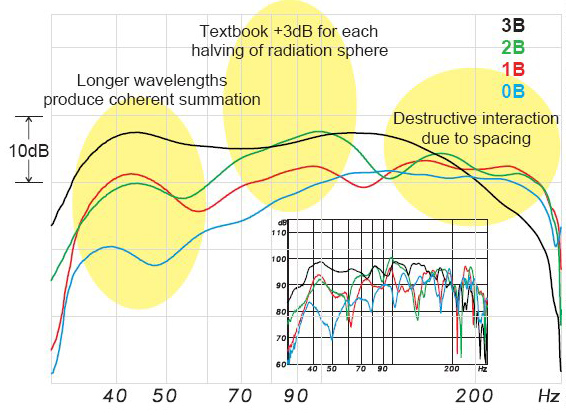
Sorry, typo above... Boost is NOT uniform over the FR. This is the most relevant source I could find.
My point was that the rear wave per driver is less than it would be if it was fewer drivers. So the smaller absolute magnitude per driver should be helpful as opposed to if the same SPL was being produced by fewer drivers. Point is related to my thought around not approaching the SPL limits of the drivers but instead distributing that energy across a greater area which should be favorable, correct?
The rearwave will be just as loud as the front wave when it leaves the driver, the number of drivers and excursion doesn't change anything in your favour.
My point was that the rear wave per driver is less than it would be if it was fewer drivers. So the smaller absolute magnitude per driver should be helpful as opposed to if the same SPL was being produced by fewer drivers. Point is related to my thought around not approaching the SPL limits of the drivers but instead distributing that energy across a greater area which should be favorable, correct?
The green has a Q of 0.8 and has a very slight rise to the low end which is hard to see given the scale of the graph. A single driver is pushed to x-max with 18 watts. This is my cabinet modelled.
The yellow is the dimensions you gave to start with of 125mm triangular sides, 176mm baffle. Q of 0.98. You get a slight boost in output from the cabinet from mid frequencies down until you get to 250Hz then it starts to drop. From 100Hz on down you are almost 6dB less in output. The excursion is less so you can put in more power but to get back to the same point you need to put in 72 watts instead of 18 (x2 then x2). Two problems, first you are now way over the thermal limit of the driver and will cook it, this is only one driver so instead of say 250W to drive the 25 you now need over a kilowatt to get back to the same output. Second that is a lot more power and the amp may not perform so well increasing thd but you can't use it anyway because of point one!
This is how easy it is to think you can eq your way out of trouble unless you work out just what other compromises you make to get there.
The Fs of the TC9 is 125Hz sow however you use it you will be using it well below it's free air resonance. Wesayso's distortion seems OK to me. It certainly rises lower down, but most subwoofers are not actually that low in distortion anyway so to better the array by themselves will need a high quality low distortion woofer. For home theatre almost any sub would blow them out of the water as power is king for LFE.
Sorry, missed your point re: power the first time I read it. I see your point around EQ-ing out of trouble. Question similar to my previous post is what this means from an SPL perspective? It looks like with 18W, one driver is already close to 100dB (which is high for prolonged exposure). So with 50 drivers, there's no way I'd come close to xMax. Lets assume we distribute that SPL equally across those drivers for the same SPL. Is it true that each driver would need 0.36W? If that's the case, then to make up the 6dB drop, then each driver would need .36 x 2 x 2 = 1.44W. So plenty of headroom on both the drivers and the amps.
I'm still a novice at this so please correct my logic or grasp of the concepts.
This is great, thanks. A couple questions.
I get the iron law. But how relevant is the loud dimension? I don't feel like I've will have much opportunity to test the limits of the array's loudness. With one driver able to handle 30 W RMS AND 50 total drivers at 89 dB/W at 1M, it seems like it's not really a sacrifice per se. Sure, I won't be maximizing the potential of the drivers. But that's one benefit for building an array in the first place. Is that the right analysis for SPL headroom?
For the response, how does the corner loading impact the lower frequencies in particular? From Murphy, he claims a 12dB boost for the line array but I've read 9dB elsewhere. Shouldn't that also help? As a matter of fact, if the magnitude is in the right ballpark, mine in the corner should be close to yours away from the corner if I'm reading your graphs right. I know the. Boost is uniform over the frequency range (couldn't find a graph that tested this for a line array).
So many concepts mixed up together, let me see if I can break it dow a bit.
Do not view those graphs as anything other than a comparison as to what you get out for what you put in. EQ and positioning can change the outcome significantly. What it does show is that below 250Hz the output rolls off for a single driver, so the low frequency output will need to be boosted to have a flat response down low.
When the Q of the cabinet is raised by the cabinet being smaller the air spring behind the driver become stiffer. This is why the excursion is less for a higher Q cabinet, it controls the cone more. The downside to that is that the frequency rolls off higher up. A small cabinet is ideal for a high output mid driver as the low frequency extension isn't needed and the cone control limits excursion.
How loud you need to go ultimately depends on you. You might run from the room screaming at 90dB you might be the type of person who is trying to turn up the volume at 110dB, I don't know.
What I do know is this, as you mention below the efficiency and sensitivity gain is not uniform with frequency in a line array, some areas are boosted others dip down. The corner position will also help in the lower octaves.
By the time you get to the high frequencies you are back down to basically what a single driver alone would produce. Most people are tilting down the frequency response by roughly 6dB so if a single driver can get to 100dB before reaching maximum linear excursion you could expect the line to produce output up to 106dB within it's linear range.
Regardless of the corner position, EQ, cabinet size etc you will almost certainly run out of excursion at the lowest frequencies if you want to be flat to 20Hz or so and have enough amp power to keep turning the volume up.
What you need to think about now is peak vs constant spl. This is not a jack hammer or an aircraft the spl will not be constant unless you plan to listen to sine waves by themselves.
Music and movies are mixed with a certain amount of dynamic range. The difference between the lowest and highest points in the track. There can easily be a difference of 20 to 30dB in movies between dialogue level and explosion level. To have the dialogue coming out at 70dB means that you would need to be able to produce 100dB to handle that peak without clipping or distortion.
Music has much less dynamic range these days but it still has some. On my systems I need to turn up the volume much more when listening to movies than music as the average level of the dialogue is so much lower compared to the average level of the music. Make sense?
Have a look at THX refernce levels to give you an idea of the type of peak capacity the recommend for playing movies. You may or may not need that much.
So with 50 drivers, there's no way I'd come close to xMax. Lets assume we distribute that SPL equally across those drivers for the same SPL. Is it true that each driver would need 0.36W? If that's the case, then to make up the 6dB drop, then each driver would need .36 x 2 x 2 = 1.44W. So plenty of headroom on both the drivers and the amps.
The calculation at the bottom won't work that way because the gain is not over the whole frequency spectrum.
For the response, how does the corner loading impact the lower frequencies in particular? From Murphy, he claims a 12dB boost for the line array but I've read 9dB elsewhere. Shouldn't that also help? As a matter of fact, if the magnitude is in the right ballpark, mine in the corner should be close to yours away from the corner if I'm reading your graphs right. I know the. Boost is uniform over the frequency range (couldn't find a graph that tested this for a line array).
This image from OPC probably gives you the best idea of the kind of EQ that is needed to get back to roughly flat. RA 7 also had some raw responses in his thread which would help to predict what the benefit of the wall placement does.

Before I designed and got my cabinets cut, I read through all of the line array threads some a few times over and thought long and hard about it. I could have built corner mounted cabinets but I didn't, that should tell you that for me I chose a different set of compromises.
My point was that the rear wave per driver is less than it would be if it was fewer drivers. So the smaller absolute magnitude per driver should be helpful as opposed to if the same SPL was being produced by fewer drivers. Point is related to my thought around not approaching the SPL limits of the drivers but instead distributing that energy across a greater area which should be favorable, correct?
In my mind the output of 25 drivers vs one is irrelevant to this discussion. The same cancellation and distortion occurs at all levels as it is the strength of the backwave vs the strength of the front wave coupled with time delay from distance that creates the issue.
All I can say is make the distance as much as you can (within reason) and stuff or absorb as well as you can in that distance.
The only way to tell for sure if it is an issue is to make a test enclosure and measure that in comparison to a bigger enclosure vs the raw response of the driver on a big flat baffle.
If you can measure or hear some kind of disturbance then you have your answer. These sort of cabinet induced problems are often described as a boxy sound or something just not seeming to be right with the sound.
Phew, I hope this helps.
Wow, very thorough! Thanks fluid, super helpful! I re-read RA7's thread too and started thinking about what other creative solutions would be worth considering to get the drivers close to the wall with as narrow a baffle as possible and still get the volume as close to 2L as possible. The comments around how well integrated the bass is with the arrays (I think by OPC) were compelling.
First, I'm wondering if I should reconsider the concept I had brought up a while ago.
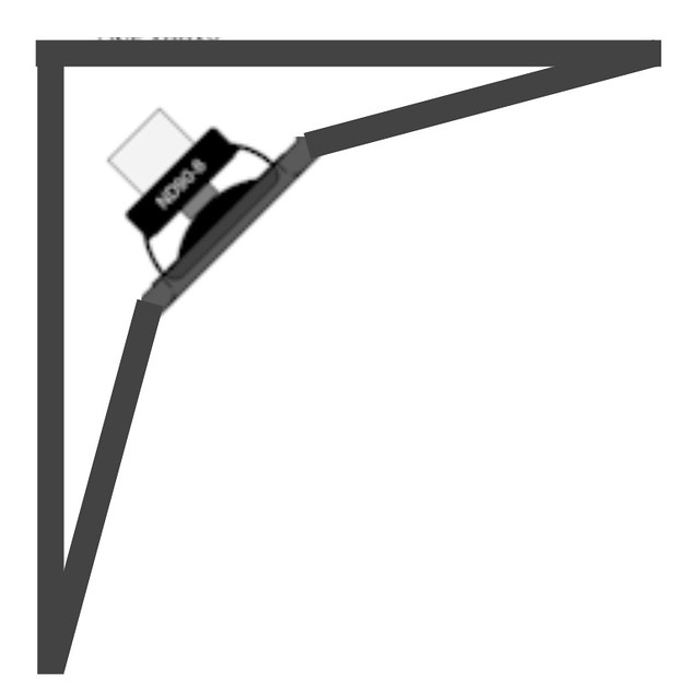
It's certainly more complicated to build and I'm not sure if the extra junctions/facets would be worth the tradeoff. Also, it starts to get further away from a true corner loaded driver and starts to look like an infinite baffle. The back wave might be better handled if I can deflect towards the acute corners which would be stuffed with fiberglass. Bracing would be difficult as well.
Second, I could use fewer drivers so there's more volume per driver. IIRC, if you had 75% of the room height covered, you would be ok generally speaking. As such, I could use 20 drivers and be in that ballpark. This wouldn't get me all the way to 2L by itself though.
Third, instead of centering the drivers vertically in the corner, I could have them start at the ceiling and then build a hollow "base" so to speak that the tower is connected to. I'd need to play with the design to make sure it didn't look funky. Also unlikely to get all the way to 2L with this alone.
Fourth, a similar concept would be to go through the other side of the wall where there's simply garage space and perhaps have a ~4" hole that is connected to a length of 4" PVC pipe (with an elbow) that is stuffed with fiberglass and capped at the end. As long as it's capped, no issues with pipe resonances? It just acts as more cabinet volume? Or it could be simply a cut out that just leads to a hollow box mounted on the wall. This would be invisible to the room, I could get the volume to whatever I wanted basically, and it could even be adjustable. I could perhaps even get the baffle even smaller although I'm wary of that given the back-wave concern. It's effectively the same as building these into the wall, but simpler to execute since I don't need to actually mess with the walls themselves. It's more of a tack-on. Messing with the walls is also an option of course.
Just brainstorming here... would love any reactions or other ideas.
First, I'm wondering if I should reconsider the concept I had brought up a while ago.
It's certainly more complicated to build and I'm not sure if the extra junctions/facets would be worth the tradeoff. Also, it starts to get further away from a true corner loaded driver and starts to look like an infinite baffle. The back wave might be better handled if I can deflect towards the acute corners which would be stuffed with fiberglass. Bracing would be difficult as well.
Second, I could use fewer drivers so there's more volume per driver. IIRC, if you had 75% of the room height covered, you would be ok generally speaking. As such, I could use 20 drivers and be in that ballpark. This wouldn't get me all the way to 2L by itself though.
Third, instead of centering the drivers vertically in the corner, I could have them start at the ceiling and then build a hollow "base" so to speak that the tower is connected to. I'd need to play with the design to make sure it didn't look funky. Also unlikely to get all the way to 2L with this alone.
Fourth, a similar concept would be to go through the other side of the wall where there's simply garage space and perhaps have a ~4" hole that is connected to a length of 4" PVC pipe (with an elbow) that is stuffed with fiberglass and capped at the end. As long as it's capped, no issues with pipe resonances? It just acts as more cabinet volume? Or it could be simply a cut out that just leads to a hollow box mounted on the wall. This would be invisible to the room, I could get the volume to whatever I wanted basically, and it could even be adjustable. I could perhaps even get the baffle even smaller although I'm wary of that given the back-wave concern. It's effectively the same as building these into the wall, but simpler to execute since I don't need to actually mess with the walls themselves. It's more of a tack-on. Messing with the walls is also an option of course.
Just brainstorming here... would love any reactions or other ideas.
Last edited:
No problem, glad it helped.Wow, very thorough! Thanks fluid, super helpful!
Agreed.The comments around how well integrated the bass is with the arrays (I think by OPC) were compelling.
I think this idea has merit as I much prefer the idea of creating a waveguide that smooths the wall transition and starts at the edge of the driver frame. I would still use felt at the edges near the wall, this works well with horns to reduce diffraction.First, I'm wondering if I should reconsider the concept I had brought up a while ago.
The back wave might be better handled if I can deflect towards the acute corners which would be stuffed with fiberglass. Bracing would be difficult as well.
I would try to push the baffle as far away from the corner as you are willing to go. The distance is too short for any sort of diffusion to work, absorption is the way to go. I would combine this with the idea of a stiff standalone baffle that is isolation mounted and sealed to the shape that forms the enclosure.
Second, I could use fewer drivers so there's more volume per driver. IIRC, if you had 75% of the room height covered, you would be ok generally speaking. As such, I could use 20 drivers and be in that ballpark. This wouldn't get me all the way to 2L by itself though.
I would do the opposite and use 25 drivers in a smaller volume than 20 with more.
I would put them as close to the floor as you can. You will get the most benefit from floor coupling, ceiling reflections can also be more objectionable than floor. Even though the array has some vertical directivity to reduce both reflections.Third, instead of centering the drivers vertically in the corner, I could have them start at the ceiling and then build a hollow "base" so to speak that the tower is connected to. I'd need to play with the design to make sure it didn't look funky. Also unlikely to get all the way to 2L with this alone.
You may well end up creating some kind of helmholtz resonsnace like a vented enclosure which could then interfere, this is really difficult to predict the result without using something like akabak to model it. I prefer simple where possible.Fourth, a similar concept would be to go through the other side of the wall where there's simply garage space and perhaps have a ~4" hole that is connected to a length of 4" PVC pipe (with an elbow) that is stuffed with fiberglass and capped at the end. As long as it's capped, no issues with pipe resonances? It just acts as more cabinet volume?
You may well end up creating some kind of helmholtz resonsnace like a vented enclosure which could then interfere, this is really difficult to predict the result without using something like akabak to model it. I prefer simple where possible.
Yes, this is what I was afraid of. Extending the volume through a larger hole and box would be less risky though, correct?
With all of the power available in JRiver (being able to adjust just about anything to your hearts desire) I couldn't see any benefit in using the standard functions in an AVR.
Not even for bass management. JRiver can do it all, you only need the amplifiers function.
Full control is what I want. Just my point of view.
Not even for bass management. JRiver can do it all, you only need the amplifiers function.
Full control is what I want. Just my point of view.
Yes, trough my Xonar Essence ST + add-on card. The NVidia Quadro video card can carry multichannel audio trough HDMI, the Xonar ST card has it's own SP/dif output that can carry a multichannel signal but that's really not as interesting as it would have to be coded in AC3/DTS.
There's also a multichannel soundcard on board but that one is not up to my standards.
I selected this workstation for the PCI slot that fit my Asus card, a standard PCI slot is getting rare these days. But the ST card did perform better in tests than the STI that came after it. So I didn't want to replace it just yet.
There are several USB options available though. It would be wise to check what they can do before getting one. I know BYRTT has some experience there.
I might consider going parallel with the walls at the start with the higher frequencies, then easing onto the wall for the lows with a progressive roundover. You could add some stuffing at the tips. This way the highs won't be destined for the reflection so much as they'll be in your control.First, I'm wondering if I should reconsider the concept I had brought up a while ago.


I have a question for you all, having read this thread and much of Wesayso's line array thread. How viable would it be to do an infinite baffle version built into the wall? My room has a storage area behind the speaker wall. I suppose this approach would avoid the box sound, solve some room issues, but perhaps it would reduce the spl too much? I tried finding a thread to discuss this, but have not seen one. There was a brief mention in here a number of pages ago. I can pick this up in a new thread, but thought Id ask here first.
Thanks
Thanks
The top one, with damping at the transition would be my hunch. But I'd carefully plan the size of the wings. Could be harder on the WAF.
No sharp transitions would be my advise.
Is there any guidance or theory behind the size/shape of the wings? I could use thin kerfs in MDF to make the curves. Or I can approximate with 3-5 segments.
If you're planning on using jriver to EQ and otherwise adjust the performance I assume you can still do in wall. You won't get the corner loading benefit
I don't really understand what you mean here, Jriver can perform whatever EQ you need, the placement in wall, on wall, corner or free standing will determine what sort of boundary reinforcement you get. It doesn't have to be directly in the corner to get a significant level of reinforcement.
Edit: missed the post above that was asking about infinite baffle in wall placement makes more sense now!
Is there any guidance or theory behind the size/shape of the wings? I could use thin kerfs in MDF to make the curves. Or I can approximate with 3-5 segments.
You will be creating a waveguide just a tall thin one. The angle of the walls will set the pattern control angle, the depth will set the loading that the guide can give and the amount of roundover will help to reduce diffraction.
As to what result you will get unless you put a lot of effort into a comprehensive simulation best guesses is where you will land.
With this sort of stuff practicality and whether you can live with the look of it will probably set the boundaries for you.
Starting to go further and further from minimal visual impact!
Last edited:
This is really basic question, but what do you do if you're using a computer that doesn't have pre-outs? Sounds like your workstation has 7.1 analog outputs?
HDMI is a good option if your AVR has it, as you should be able to EQ the channels in Jriver separately before they are sent to the AVR.
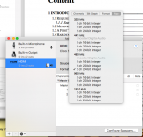
This what I get get when I plug my TV into my Macbook Pro. Only two channels because that is all the TV has, plug your Mac into your receiver to see if you have all 8 channels (assuming 7.1 AVR). If you do click on configure speakers to determine what goes where.
Attachments
- Status
- This old topic is closed. If you want to reopen this topic, contact a moderator using the "Report Post" button.
- Home
- Loudspeakers
- Full Range
- "Wall-integrated" corner loaded line array with Vifa TC9 drivers