 mieeww
I checked R19 and R20 in first order and they're OK. Any resistor I had checked (most of them) was ok. I managed to drop the DC voltage, it seems like there is no input bias set on that channel however it works totally fine. No heat, no noises, no harshes, the sound is perfect, voltage seem not to be too much for any transistor. Tried also setting to 22 Ohm resistors again and the output bias stayed OK. I got confused 
Hi, as written in manual, output RL serial filter is an optional choice, recommended to use at mainly capacitive speaker's impedance character, otherwise no need too. Simple test is to connect the speakers you're using, feed them with 10 kHz square waves and observe the ringing on scope with and without RL filter. No ringing response will tell whether to use one or there's no need to.
I connected the Wharfedale dia 10.7 and 9.5 in parallel that's 3ohm and VSSA is very stable, I'm very pleased on how it sounds. Thanks Andrej.
0,33 mho load, very tough 15x20 mm output device 

Hi, as written in manual, output RL serial filter is an optional choice, recommended to use at mainly capacitive speaker's impedance character, otherwise no need too. Simple test is to connect the speakers you're using, feed them with 10 kHz square waves and observe the ringing on scope with and without RL filter. No ringing response will tell whether to use one or there's no need to.
This is another case of RTFM...
Soooorry!
Do
see below photo.
Volume is past the middle, its loud yet the heatsink not heating up. What's wrong with this AMP!!
http://s67.photobucket.com/user/jiviking/media/SANY0122_zps3d253a2c.jpg.html
Nice face plate and audio setup!
James
A friend of mine taught me a trick during the listening to enhance the sound density on SMPS set ONLY. The idea is to enhance the current density on the ferrite ring on SMPS by 5 to 6 pcs of twisted std steel wires (AWG 24 or 22) as follow
If you don't like the sound, you can remove it anytime as it is tape on it only.
Enjoy!
James
An externally hosted image should be here but it was not working when we last tested it.
If you don't like the sound, you can remove it anytime as it is tape on it only.
Enjoy!
James
I do have 120mV between TP1 and TP2 and.. -190 between TP3 and TP4 (using the + for TP4). I checked the resistors and they're ok
Than this means TR1 is not working properly so CCS from positive rail cannot adjust its current and potential between TP3-TP4 is fixed to 190 mv. Since TP1-TP2 and TP3-TP4 are so different, the output DC voltage is 0,5 V. Check TR1 or CCS around it.
This is another case of RTFM...
Soooorry!
Do
Yeah sometimes it helps to RTFM.
A friend of mine taught me a trick during the listening to enhance the sound density on SMPS set ONLY. The idea is to enhance the current density on the ferrite ring on SMPS by 5 to 6 pcs of twisted std steel wires (AWG 24 or 22) as follow
If you don't like the sound, you can remove it anytime as it is tape on it only.
Enjoy!
James
Hey James thanks for the tip, although I don't know what could be the SQ effect of a steel wire piece inside toroid core other than amplifying magnetic field and thus potentially stronger interference filtering. Could be also negative effect since this is amplifying of stress field outside toroid core.
First One Mosfet Amplifier
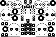
Here's just a preliminary shot of a First One Mosfet Amplifier PCB just in development process.
Some "must" features expected from the First One amp:
- 100 Wrms/8 Ohm, 200 Wrms/4 Ohm, 220 Wrms/2 Ohm
- same 3 Mhz/-3 dB bandwidth as in VSSA
- SMPS400A180 power supply per channel
- 2 Ohm normal operation
- 75 x 50 mm dual layer PCB size, copper metalized up to 110 um
Expected group buy in September.
Attachments

Here's just a preliminary shot of a First One Mosfet Amplifier PCB just in development process.
Some "must" features expected from the First One amp:
- 100 Wrms/8 Ohm, 200 Wrms/4 Ohm, 220 Wrms/2 Ohm
- same 3 Mhz/-3 dB bandwidth as in VSSA
- SMPS400A180 power supply per channel
- 2 Ohm normal operation
- 75 x 50 mm dual layer PCB size, copper metalized up to 110 um
Expected group buy in September.
Hi LC,
Could -/+50Vdc rail fit? => i have a second Rcore pair (500Va 2x0-120V pri/2x36Vac sec) that are waiting for a project....
Marc
Last edited:
VSSA Crappy Mode
Hi,
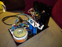
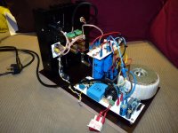
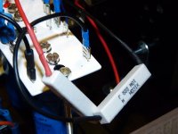
This morning i go foward to stage "ready to adjust" for the first chassis test. The second is on way but still need a little more work. On last serie picture my 22R pactch wire for first power on...
Marc
Hi,
This morning i go foward to stage "ready to adjust" for the first chassis test. The second is on way but still need a little more work. On last serie picture my 22R pactch wire for first power on...
Marc
Attachments
Hi LC,
Could -/+50Vdc rail fit? => i have a second Rcore pair (500Va 2x0-120V pri/2x36Vac sec) that are waiting for a project....
Marc
Yes it would fit for the output stage. Also you will need separate +/-10 V/100 mA higher PSU for front-end, so the outputs can clip at max rails potential, no voltage lost on the outputs.
Yes it would fit for the output stage. Also you will need separate +/-10 V/100 mA higher PSU for front-end, so the outputs can clip at max rails potential, no voltage lost on the outputs.
No soucy...
Marc
- Home
- Vendor's Bazaar
- VSSA Lateral MosFet Amplifier