So how does this setup sound? Very tube like. No booming bass, but great vocals and sound stage. It really is a tube amp w/ the output tubes and transformer replaced by a balanced MOSET source follower. To my ears this is a great hybrid approach since it essentially behaves like a 2 X 110 Watt tube amp. I hear detail I never heard before...! -
Cheers,
D. [/QUOTE]
I think no booming bass but great vocals is ok but it isnt linear compare to original, isnt it better to design linear hybrid tube amp with booming bass and great vocals ?
Cheers,
D. [/QUOTE]
I think no booming bass but great vocals is ok but it isnt linear compare to original, isnt it better to design linear hybrid tube amp with booming bass and great vocals ?
Hi Kenpeter,
what for is L1?
Please describe how to make it in practice,
Its a choke. Not entirely out of character for a tube amp?
Maybe satisfies "No Loop Feedback" better than a servo?
The purpose merely to center the DC. As gates are pulled
away from center by high impedance currents on both ends,
without some kind of servo would never quite exactly equal
GND in the middle. Probably drift to one rail or the other...
Since I'm too stupid to figure out how to make an actual
op-amp servo work. Nor did my copy of Apex' servo work
(cause I probably copied something wrong?) I've shorted
DC to GND through the choke and make the output stage
to follow choke DC instead. There might be a small offset,
but nothing dangerous. Its a dirt simple cheat is all...
I got 600ohm telephone transformer here in my hand that
measures 2H per side. 8H for series wound on same core.
Its an old Stromberg Carlson, potted in small metal can,
maybe slightly overbuilt too well for telephone? But I think
an item of this sort is not too far out of reach?
I'm sure its not made to withstand serious DC saturation,
but amount of current needed to keep a solid GND in the
middle is only the difference between the two CCS. Less
than 1mA. Any audio choke or transformer winding 1H or
more should be fine. Not asked to do anything challenging.
If ever conducting enough DC current to get saturated,
loss of AC impedance to audio signal will be the least of
your worries. As long as it can take the full CCS 20mA
without melting or burning, and holds GND. I don't care
if this choke saturates in such an emergency.
Last edited:
I tried and tried to simulate your OP-Amp based servo.
Both as originally drawn, and with every tweak I could
imagine to try and "fix" it... Maybe some other changes
I've made elsewhere were incompatible w this servo?
Tried several LT op-amp models as substitute for TL071
QUOTE]
Do you try to use 50k trimpot for DC offset instead TL071 servo?
No, but I should have...
I notice with an Inductor, that LTSpice computes the wrong
initial operating points. Takes several hundred fully simulated
mS for the output stage to stabilize at GND. But it eventually
does, and works fine thereafter...
LT maybe has similar issue confusing the op-amp? If such a
device model is initially asked to handle unrealistic operating
points, who knows what happens? But it sure doesn't settle
for me, and the computations want to take forever...
May be something about this output topology that is hard to
compute initial DC? I don't know what would be confusing it.
I don't think a real circuit (servo or inductor) would have any
such problem.
Last edited:
Oh: And several seem to have ants about IP ownership?
"Don't use for commercial" and all that garbage... I am
not one who loves IP law. Idea that only the filthy rich
can own and use their own ideas (and claim to a hoard
of other people's ideas) offends me.
Use it, abuse it, paint a mustache on it, sell it. Ideas
are not property for evil squatters to sit upon and do
nothing but collect ransom. If one or more of my ideas
makes you money, I only want to brag about it on my
next resume.
Last edited:
Oh: And several seem to have ants about IP ownership?
"Don't use for commercial" and all that garbage... I am
not one who loves IP law. Idea that only the filthy rich
can own their own ideas (and hoard other people's ideas)
offends me.
Use it, abuse it, paint a mustache on it, sell it. Ideas
are not property for evil squatters to sit upon and do
nothing but collect ransom. If one or more of my ideas
makes you money, I only want to brag about it on my
next resume.
I have taken 15 years to develop a CAD package so dont understand why I should just give it away.
I have also designed numerous amplifiers and again dont see why I should just give the design away.
If I have worked hard to design things then I should be allowed to sell them without people stealing from me.
Yes, you should be allowed. And not find someone with more money
claim some trivial part of your greater idea out from under you, and
put you out of business unless you can cough up equal or greater
money to fight back.
If patents and copyrights were free: But require that you either use,
support and update the idea, and/or licence for reasonable low fee
to anyone and everyone. Then I might not find them offensive. Too
many bad actors hold the worlds ideas hostage to no good purpose,
and bad caretakers of ideas should be stripped of that undeserved
privilege.
The current systems are not accessible and do nothing to defend
the poor artist or inventor against IP slavery to the rich. The best
I can afford is post my ideas and designs to the public domain. To
complicate efforts of others to steal claim over them.
If we are gonna go at it, I'm OK with move this to another thread.
Last edited:
If we are gonna go at it, I'm OK with move this to another thread.
Maybe better stick to the topic
")

Hi Kenpeter
I am astonished how good you designed pre,
kind of art,
but deleting C2
much improves thd
with the same voltage swing...
and still did not understand
why load pre with L?
To be able to drive the output MOSFETs all the way to the rail. The voltage is higher than absolutely necessary but it is easy to get from the existing transformer supplying the 50V rails, by use of a voltage doubler.
Regarding the use of an inductor, it is needed to provide zero DC. The inductor will act as a rising impedance for AC, something which the pre stage should be able to drive in the frequency range of interest. However, DC currents will pass to ground with relatively little resistance, and thus provide a DC ground reference.
Regarding the use of an inductor, it is needed to provide zero DC. The inductor will act as a rising impedance for AC, something which the pre stage should be able to drive in the frequency range of interest. However, DC currents will pass to ground with relatively little resistance, and thus provide a DC ground reference.
Last edited:
Hi Kenpeter
I am astonished how good you designed pre,
kind of art,
but deleting C2
much improves thd
with the same voltage swing...
and still did not understand
why load pre with L?
L1 not intented to load AC signal. Of course it will to
some extent, but not because I actually wanted it to.
Only for absolute centering DC between CCS without
aid of a servo loop.
C2 in pre-amp does absolutely NOTHING if Loftin White
is tuned correctly to cancel cathode negative feedback.
But that tuning is tricky, and could accidently become
a positive feedback without C2. Harmless insurance.
The rail voltages were chosen by APEX. I'm just working
within his bill of materials to the greatest extent possible.
Even transistor substitutions are only temporary stand-in
till I find matching Spice models.
+/-90 does seem a little high for gate pull-ups? But I have
hope that I might power the triode with that same 180V...
Just not sure how to do that without creating PSR issues?
It is a Loftin White stage, so PSR might be a cancellable?
+/-90 does seem a little high for gate pull-ups? But I have
hope that I might power the triode with that same 180V...
Just not sure how to do that without creating PSR issues?
It is a Loftin White stage, so PSR might be a cancellable?
I did this with one of my designs.
The MOSFETs ran off +/-60V and I got 120v for the valve stage.
I put in an RC dropper to the B+ and B- rails and it works very well.
I think there might be way to direct couple and do away
with both C4 and L1, but I won't have time to draw and
run that sim tonight.
Borrow an idea from MJK, and resistively bias Q1's emitter
to a fixed DC reference (like -0.7VDC). AC coupled to the
Triodlington. This should hold DC at GND for the Mu follower,
even with the triode not yet fully warmed. And from there,
straight into the emitters of the crossing correction circuit.
Last edited:
OK.. This is with MJK style plate load:
Gyro with long time constant centers
on a voltage rather than a true CCS.
I havn't decided V1 should be diodes,
transistors, a lead acid cell, a servo???
Choice of reference probably matters
less than small problem that Q1's base
current can pump the result offcenter
slightly when output is near rail to rail.
I havn't figured if this warrants a more
complicated fix? Its not a huge offset.
Another weakness of this gyro circuit
is that it can only pull the resulting DC
upward. Means gate CCS will have to
be deliberately mismatched slightly in
favor of pulling the center node down.
The inductor and 47uF coupling cap
are gone. A new coupling cap of 1uF
takes its place elsewhere. So another
potential win for cap quality?
But input sig is now ref to -90rail?!? How
to flip input down to -90 with good PSRR
could be input transformer or something
P-JFET??? I don't see Loftin White alone
capable to fix PSRR in dual rail situation.
Input transformer could be a good break
for any ground loop too, if that matters?
And won't need the +250 supply anymore.
Check it with plate disconnected to fake
the cold start. 60mV offset... All good.
Attachments
Last edited:
I used a similar to this
http://geek.scorpiorising.ca/contrib/Geek/Hybrid_mu-follower_ECC812.png
for some years.
And about the fets, you might want to use FQA12P20. and so on but if you've got irf already I wouldnt bother replacing them
If I recall correctly I used 6N1P in my hybrid.
Also, why not introduce some global feedback..
You are completely right! Q1+Q8 are not even needed.
Q1's function now irrelevant due to cap coupled gyro.
Q3 base bias is all that matters... Upper half gyro sets
Voltage. Rule of 1/(Mu-1) and Triodlington's cathode
resistor sets current.
We can almost certainly drop some dead wood parts.
Exactly what I was looking for...
IRF240 for q3 gets rid my base diode pumping problem.
Last edited:
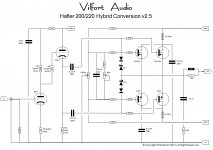
MOSFET/Tube hybrid verision 2.5
Pawel,
Here is a cleaner version of the schematic. You should be able to see the crossing and connection of wires more easily. I also fixed a drawing mistake on the source/drain connections. This is indeed a source follower output stage.
If you want to build from scratch rather than using an old Hafler, then the Renesas SK1058/SJ162 MOSFETs would do nicely in the output stage.
D.
Attachments
- Status
- This old topic is closed. If you want to reopen this topic, contact a moderator using the "Report Post" button.
- Home
- Amplifiers
- Solid State
- Tube/Mosfet 100W Hybrid Amplifier