There are some pretty highly regarded hybrids out there now, some examples are Pathos, Vincent, Unison Research and I think there is one made by Lamm.
The counterpoint amp has a nasty reputation of going volcano, which is strange as I have found the Hitachi mosfet's to be very robust.
However Iam not sure the SRPP is the way to go as the circuit tends to have a rather high output impedance to be driving the gate capacitance of mosfets.
The counterpoint amp has a nasty reputation of going volcano, which is strange as I have found the Hitachi mosfet's to be very robust.
However Iam not sure the SRPP is the way to go as the circuit tends to have a rather high output impedance to be driving the gate capacitance of mosfets.
First decision, are you planning on a normal design with lots of global feedback or low or no global feedback? if you are looking at a no feedback design simpler circuits can be used because of need for lessor amounts of gain.
There is a hybrid over in the hafler dh200\dh220 thread that looks promising.
Although I think I will add a bias regulator if I go that way.
There is a hybrid over in the hafler dh200\dh220 thread that looks promising.
Although I think I will add a bias regulator if I go that way.
Why two VBE multipliers in series bias?
Valve V2 WCF seems wasteful/redundant.
Or maybe its V1b that is the redundant valve?
Only needs one style unity follower or the other.
Two or three twin triodes at most for stereo,
rather than four.
I'd even be tempted to replace V2b with solid
scrape transistor. That valve acts upon strong
local feedback and not behaving much like you
expect from the plate of a triode anyway...
If poster above is so worried that 240/9240
might not sound good as compliments? You
could abuse your BC327/337 current limiters
as crossing error correctors. And add a pair
of Schottky diodes in series with your 0R47
to act as the square law current detectors.
No problem to make diodes match, and any
power compliment mismatch is corrected.
The source resistor linearizes both MOSFET
square law curves too much anyway, that
smooth AB crossing without some form of
additional error correction near impossible.
240/9240 mismatch is not the main problem,
excessive crossing linearity is the problem.
You get that same issue with any device but
maybe lateral mosfet, because you need the
source or emitter resistor for other reasons...
Plenty of amps built with no corrections aside
from NFB hide the problem acceptably. But I
see no global feedback loop in this amp. So you
are gonna want to smooth out the crossing for
sure...
----------
"Error correction" is probably a misleading term.
"Complimentary curve correction" makes more
sense...
Last edited:
Please go to post #17,First decision, are you planning on a normal design with lots of global feedback or low or no global feedback? if you are looking at a no feedback design simpler circuits can be used because of need for lessor amounts of gain.
There is a hybrid over in the hafler dh200\dh220 thread that looks promising.
Although I think I will add a bias regulator if I go that way.
Regards
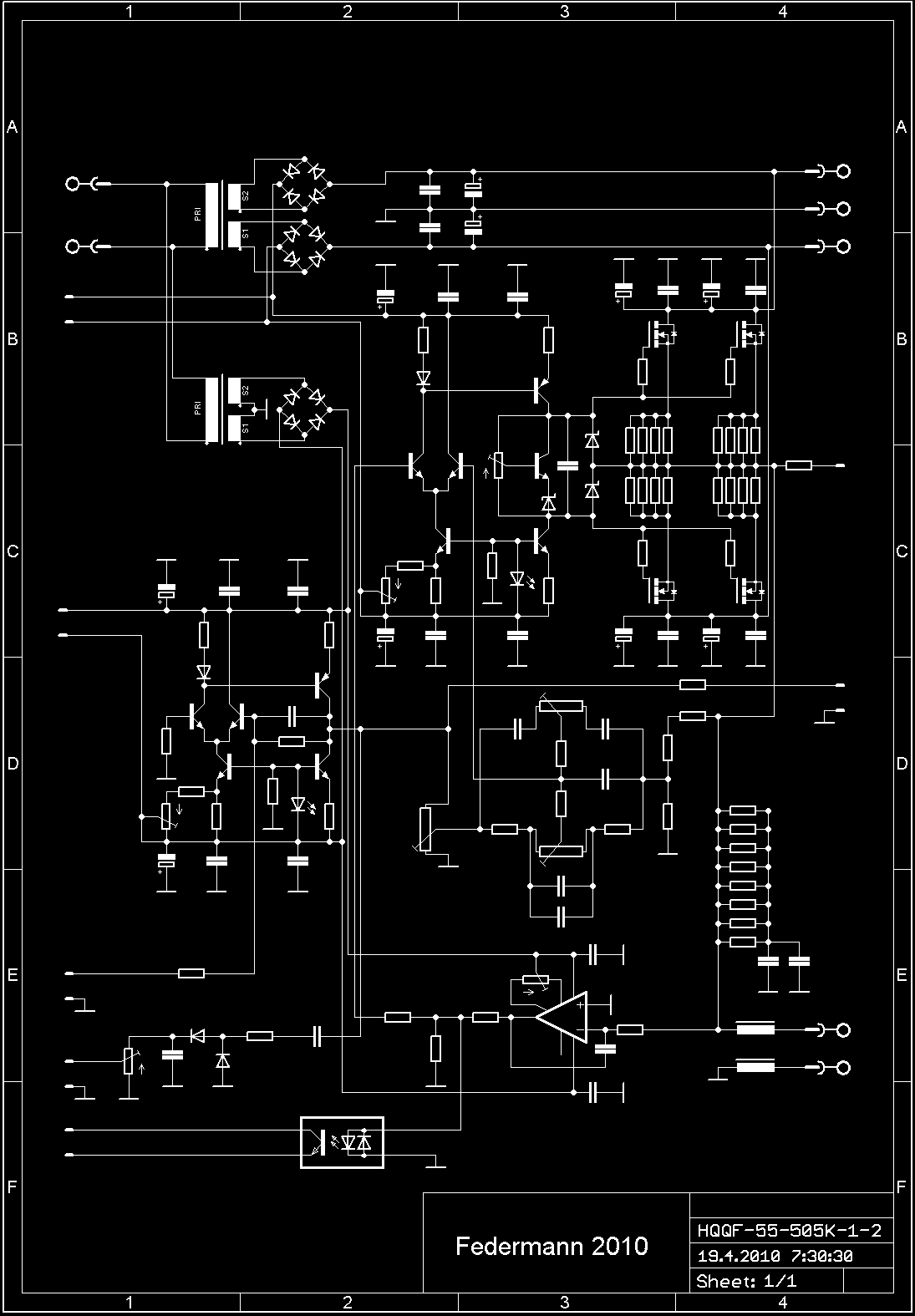
When amplifier was tested, I will share schematics for give idea to other people, but PCB and other specification is not for share.o.k I should have looked at your drawing in post 17 .
BTW is this a DIY project or are you developing a commercial product?
they are two different animals you know.
No difference of concern to me. So long as he's sharing/
teaching/learning and not simply marketing. Development
of commercial products is interesting when it completely
open to DIY on the side (like PASS). Apex has the right
attitude, I appreciate that moderators give him leeway.
teaching/learning and not simply marketing. Development
of commercial products is interesting when it completely
open to DIY on the side (like PASS). Apex has the right
attitude, I appreciate that moderators give him leeway.
There will be some change to keep amplifier simple.Why two VBE multipliers in series bias?
Valve V2 WCF seems wasteful/redundant.
Or maybe its V1b that is the redundant valve?
Only needs one style unity follower or the other.
Two or three twin triodes at most for stereo,
rather than four.
I'd even be tempted to replace V2b with solid
scrape transistor. That valve acts upon strong
local feedback and not behaving much like you
expect from the plate of a triode anyway...
If poster above is so worried that 240/9240
might not sound good as compliments? You
could abuse your BC327/337 current limiters
as crossing error correctors. And add a pair
of Schottky diodes in series with your 0R47
to act as the square law current detectors.
No problem to make diodes match, and any
power compliment mismatch is corrected.
The source resistor linearizes both MOSFET
square law curves too much anyway, that
smooth AB crossing without some form of
additional error correction near impossible.
240/9240 mismatch is not the main problem,
excessive crossing linearity is the problem.
You get that same issue with any device but
maybe lateral mosfet, because you need the
source or emitter resistor for other reasons...
Plenty of amps built with no corrections aside
from NFB hide the problem acceptably. But I
see no global feedback loop in this amp. So you
are gonna want to smooth out the crossing for
sure...
----------
"Error correction" is probably a misleading term.
"Complimentary curve correction" makes more
sense...
Only one bias transistor is on heatsink.
Thank's for understand, I not advertising and sell anything on this forum, just share what I want to share, that only can be useful for other people.No difference of concern to me. So long as he's sharing/
teaching/learning and not simply marketing. Development
of commercial products is interesting when it completely
open to DIY on the side (like PASS). Apex has the right
attitude, I appreciate that moderators give him leeway.
Regards
However Iam not sure the SRPP is the way to go as the circuit tends to have a rather high output impedance to be driving the gate capacitance of mosfets.
V2 appears to be a White cathode follower.
If so, the output "impedance" is quite low.
On the other hand, there is a very low limit
how much current can be pushed or pulled
by an ECC88. And it may not be enough...
Slew rate limited, is that the right term???
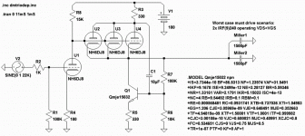
I figure +/- 4mA per gate at 22KHz. Bob Cordell
recently warned me that figure actually rises if
operated into VDS less than VGS. I sim this with
1500pF Miller sandbag, get +/- 10mA at 22KHz?
And this design must be driving FOUR such gates,
but only 2 into VDS<VGS Miller trouble at a time.
Suppose Apex were to parallel V1b, V2a, V2b?
and replace the current V2b location with a
transistor (and the appropriate bias resistors).
Triodlington also comes to mind...
Last edited:
Looking at apexaudio's schematic in post 17, I cannot help wonder why two cathode followers after each other is needed? The white cathode follower is not difficult to drive. Try without the white cathode follower first. That will likely sound very sweet (I am listening to a similar setup w/ 6SL7 as amplification and 6SN7 as cathode follower). Trick is to run the CF tube at high current.
Then again, if we need more gain here, I would opt for an Akaido arrangement. However some hate the sound of SRPP. So perhaps cascading the first two triodes and then keeping the white cathode follower (Moscode 300 style) is the way to go. - Heck, try building all three and see what sounds best. J
Then again, if we need more gain here, I would opt for an Akaido arrangement. However some hate the sound of SRPP. So perhaps cascading the first two triodes and then keeping the white cathode follower (Moscode 300 style) is the way to go. - Heck, try building all three and see what sounds best. J
Thank's, good adviceLooking at apexaudio's schematic in post 17, I cannot help wonder why two cathode followers after each other is needed? The white cathode follower is not difficult to drive. Try without the white cathode follower first. That will likely sound very sweet (I am listening to a similar setup w/ 6SL7 as amplification and 6SN7 as cathode follower). Trick is to run the CF tube at high current.
Then again, if we need more gain here, I would opt for an Akaido arrangement. However some hate the sound of SRPP. So perhaps cascading the first two triodes and then keeping the white cathode follower (Moscode 300 style) is the way to go. - Heck, try building all three and see what sounds best. J

I mean IRFP240/9240 are not really complementary devices, it sound horribile in mosfet amp...... BJT Design Sound better compare to IRFP240/9240
we have test it in Mosfet amp and in my opinion IRFP240/9240 is no go in mosfet amp
I am with IRFP240PbF and IRFP9240PbF very satisfied.
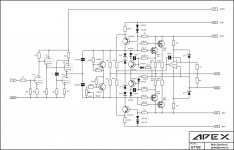
Not you, silly! The other needlessly enormous schematic with no part values...
Oh whatever...
This is any one of several ways one might do the front end to drive +/- 20mA
at 22KHz. If Cordell's extra 1500pF Miller for IRF240 when VDS<VGS is believed?
This obviously would seem way overkill if the non-linear capacitance is ignored.
I'm not at all sure that 1500pF sandbags accurately model the problem, if this
extra capacitance only appears dynamically. I'm just guessing this is how you
might assure you are covered for it?
Dmtriodep library included in the zipfile is always credit to Duncan Amps.
I have not checked to see that my copy is current against the official one.
Visit his page for the real thing. NH means "No Heater"
I probably didn't pick the optimal high voltage transistor either...
Just used one I happen to have a spice model on short notice.
I thought of it too late. R5 probably shoulda been a white LED...
Attachments
Last edited:

If I ever design or build a commercial product. I assure you,
would be priced so stOOpid high, only audiophools with more
money than common sense (and no DIY skills) would dream
to buy it.
I'm not sure that my attitude is right. But when I see David
Berning ask $30,000 for an amp. I think, thats the market I
want to be stealing from.
When I was network admin for Prospera Financial, I met tons
of people with disposable income and no clue... As a satellite
installer, I've been in the homes and AV rooms of billionaires.
And seen how they purchase needlessly expensive audio carp
to act like they know something about it the rest of us don't.
I will make amps for THEM. Great amps. Needlessly expensive
of course... Plenty of audiophool bragging rights to go with
just being able to afford one of the half dozen or so I would
make per year.
OK, I didn't say it was an entirely sane plan.
Last edited:
- Status
- This old topic is closed. If you want to reopen this topic, contact a moderator using the "Report Post" button.
- Home
- Amplifiers
- Solid State
- Tube/Mosfet 100W Hybrid Amplifier