In commercial audio first find good manager and lawyer, then design nice case for amplifier, and that's all, circuit is no metter at all.If I ever design or build a commercial product. I assure you,
would be priced so stOOpid high, only audiophools with more
money than common sense (and no DIY skills) would dream
to buy it.
I'm not sure that my attitude is right. But when I see David
Berning ask $30,000 for an amp. I think, thats the market I
want to be stealing from.
When I was network admin for Prospera Financial, I met tons
of people with disposable income and no clue... As a satellite
installer, I've been in the homes and AV rooms of billionaires.
And seen how they purchase needlessly expensive audio carp
to act like they know something about it the rest of us don't.
I will make amps for THEM. Great amps. Needlessly expensive
of course... Plenty of audiophool bragging rights to go with
just being able to afford one of the half dozen or so I would
make per year.
OK, I didn't say it was an entirely sane plan.
Regards
I know many audiophiles who even don't want to hear diy amplifiers, and afraid to connect diy amp on their speakers. I always suggest diyers to use protect and standards of comercial product if they want to compare with brands. You can made best amplifier on the world, and nobody don't know that. In comercial amplifier U must make many compromise, and still have 100% functional amplifier,and that is hard to get.
Last edited:
OK, here's my few 0.1$ on the subject, based on a hybrid project:
1) Your servo will have a 'pumping' problem because it's time constant is not the only one in the amp. The coupling caps form another constant with the bias network (you can forget the output impedance of the Cf as this will be very low). You will need to carefully chose the time constants, and possibly limit the amount of correction the servo can deliver.
2) Gain of a single ECC88 section using a plate resistor will be on the low side for a typical 100W amp. Consider using a CCS for the plate load, this will get you the full mu of the tube - but also, your tubes will have to be matched for equal gain.
3) kenpeter's suggestion on using 3 sections of the ECC88 in parallel is a valid one. However, you might still want to use a bit of resistance in each catkode for better current sharing. You might also consider CCS loading for the follower as well.
4) Bob Cordell's suggestion of nearly 1.5nF input capacitance when Vds approaches Vgs is valid, I have found this out the hard way (to low a driving current resulting in rail sticking effects when clipping). Two pairs of IRFP240/9240 do require a fair amount of current to drive be driven correctly.
5) The sound of this amp will be, as always, determined by the harmonic spread it generates. The tube part will do this very differently compared to the MOSFET part. As it stands, you will need a fairly high bias current in order to get enough gm to make the output of the amp sufficiently low impedance, so that the amplitude modulation of this impedance does not become significant. Asymetry of the IRFP240 and 9240 will also play a part, in fact it may appeal to 'tube sound' lovers. Some form of error correction might be the way to go. You could try a few other tricks, say asymetrical source resistors on the P and N parts, or finding a single pair that delivers the required power so you can use it without source resistors. All in all, there is no feedback so you need to really work on that follower to make it linear.
The counterpoint amp has a nasty reputation of going volcano, which is strange as I have found the Hitachi mosfet's to be very robust.
However Iam not sure the SRPP is the way to go as the circuit tends to have a rather high output impedance to be driving the gate capacitance of mosfets.
The SA100 does not use lateral MOSFETs. And, the Aikido is NOT a SRPP.
3) kenpeter's suggestion on using 3 sections of the ECC88 in parallel is a valid one. However, you might still want to use a bit of resistance in each catkode for better current sharing. You might also consider CCS loading for the follower as well.
Internally, any triode is an infinite number of smaller triode paths in parallel.
The more similar these paths, less an overall averaged curve set "leans over
to the right". Yet it is entirely valid to spread this average across multiple
envelopes if you don't mind a little extra leanover. Its supposedly less noisy
in return, but I've no measurement to prove that. Already plenty resistance
here for safe/sane parallel I think? Adding cathode resistance only makes it
that much harder to drive the MOSFETs.
The cathode load is active help, as a White Cathode Follower should be.
But also self-servo'd to a convenient voltage of equilibrium. Replacement
with do-nothing CCS is possible, but loses those two important features
and cuts drive capability in half... You then probably need 6 or 7 ECC88
sections in parallel to meet the worst case Miller of the MOSFETs, and
an optimal operating point would no longer center of its own accord.
If slightly less than 1/Mu-1 portion of the drive were fed back to R1
180R as a positive feedback, this cathode would sit more nearly at a
virtual ground, and give closer to true Mu gain. This is Loftin White.
I didn't think to go that far with the drawing, maybe I should have???
I'm talking positive feedback slightly less than the negative feedback
from the cathode resistor, so the total effect upon the cathode is still
slightly on the negative side of zero. And definitely far less than +1!
Last edited:
Kenpeter, I was refering to the fact that an ECC88 is a relativelu high gm tube, and there are variations. Assuming you want to get the most current, they will be run 'hot' so some hundred ohms or even less will help, without severely compromising drive ability (and acting as part of the gate stopper, of course this depends on layout).
My apologies, it appears that I am getting senile and combined two schematics that had nothing to do with each other in my head - don't know how I missed the active load on the CF, which I can only agree is a VERY good idea as you get double the current swing.
Returning part of the current to R1 is a very neat idea to restore gain lost by the cathode resistor without having to use a bypass cap, similar to what Broskie uses in his CCDA circuit, exploiting equal currents in a grounded cathode stage followed by a follower (no pun intended") ). Here it does require a bit of a tweak, perhaps returning the emitter of the active load partially through R1 to ground?
). Here it does require a bit of a tweak, perhaps returning the emitter of the active load partially through R1 to ground?
My apologies, it appears that I am getting senile and combined two schematics that had nothing to do with each other in my head - don't know how I missed the active load on the CF, which I can only agree is a VERY good idea as you get double the current swing.
Returning part of the current to R1 is a very neat idea to restore gain lost by the cathode resistor without having to use a bypass cap, similar to what Broskie uses in his CCDA circuit, exploiting equal currents in a grounded cathode stage followed by a follower (no pun intended
). Here it does require a bit of a tweak, perhaps returning the emitter of the active load partially through R1 to ground?Yeah, but stealing an easy pfeedback sample from the emitter
resistor is kinda sabotaged by the very activeness of this load?
Might been one of my slightly less than fully baked suggestions.
Bypass cap across 180R ain't bad plan B... I just hate being all
normal and boring like that. There has to be a weirder way to
do it! One that hasn't been exploited to a point of nausea yet.
Yet I don't want to deviate too weird off Apex' plan, else it loses
relevance to the thread.
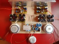
Maybe not entirely along the concept of this thread, but this is my humble contribution. Done last year by one younger member of our local forum “EnaB”. Curiosity is that I never heard this design of mine!!! I never have enough time to build and test all my designs, but thanks to a devoted small group of younger followers, new designs are prototyped from time to time.
Attachments
Maybe not entirely along the concept...
but please send a link for "EnaB" site,
Apexaudio please do not feel touched,
watching for your concept too!
@apexaudio
Yes I know this is not that type of design and therefore I tried to highlight that in my first sentence: "Maybe not entirely along the concept of this thread..." I haven't got even a minuscule intention to highjack your thread friend... just wanted to give my thoughts regarding hybrid "Tube in - Semis out" concept"! That's all!
You are doing a great service for DIY community by offering your work publicly!
@padamiecki
EnaB do not have WEB site Pawel. I just sent him an E-mail asking for permission to give his E-mail address publicly, and I am waiting for an answer. If that's OK, you'll be able to contact him directly.
Yeah, but stealing an easy feedback sample from the emitter resistor is kinda sabotaged by the very activeness of this load?
Might been one of my slightly less than fully baked suggestions.
Bypass cap across 180R ain't bad plan B... I just hate being all
normal and boring like that. There has to be a weirder way to
do it! One that hasn't been exploited to a point of nausea yet.
Yet I don't want to deviate too weird off Apex' plan, else it loses
relevance to the thread.
Yes, th eload activity can be a problem, as any output current that is not strictly proportional to the input stage current acts as feedback - and, it can also become positive feedback for eactive loads (and MOSFETs are...) but this sort of thing is something that would be nice to test in practise (simulation will not give truly representative results due to MOSFET capacitance modeling).
OK here's a free idea for you then, why not use LED bias for the input tube?
Ideally, it needs a bit more than 3V and then adjust current and if needed supply voltage for that. Why 3V? because this is the peak output voltage of a standard CD player - or, 2Vrms. Even though full mu would be enough to get 100W from a standard 1Vrms output (well, just barely), as long as there is a plate resistor, we are not going to get full mu. So, why not go to 2Vrms input for full output, be able to drive it from a variable output of a CDP - and 2Vrms is no problem for practically any line amp.
But then, let's play with the LEDs - in particular, consider 1 infra-red one in series with a green one, that will be about 3.2V at typical ECC88 currents. The beauty of using an IR LED would be that you can use an optocoupler - which gives you a very convenient way of sensing that the tubes have heated up, so you can switch on the output stage.
Another way to swing +/- 20mA into MOSFETs.
Voltage gain slightly less, that might be an issue.
Triodlington is an odd animal. Beta multiplies the
transconductance of the Triode. But Triode's rule
of Mu inherits to the BJT. The Plate is monitoring
the Collector Voltage, sneaky local feedback.
Voltage gain slightly less, that might be an issue.
Triodlington is an odd animal. Beta multiplies the
transconductance of the Triode. But Triode's rule
of Mu inherits to the BJT. The Plate is monitoring
the Collector Voltage, sneaky local feedback.
Attachments
I no expect to anybody build my project, I do that for myself, if there is something usefull for you be welcome.but please send a link for "EnaB" site,
Apexaudio please do not feel touched,
watching for your concept too!
Regards
Maybe not entirely along the concept of this thread, but this is my humble contribution. Done last year by one younger member of our local forum “EnaB”. Curiosity is that I never heard this design of mine!!! I never have enough time to build and test all my designs, but thanks to a devoted small group of younger followers, new designs are prototyped from time to time.
Roughly DOGC based with tube input
includes Pete Walker's feedforward correction. The only thing i don't like is that the output sticks to +V rail of the output until the tube heats up, but that is easily solved (see idea with optocoupler, put the LED in the LTP tail, and transistor to provide bias for the VAS CCS.You are right "ilimzn" (as usual! ) but only if someone turn EVERYTHING on at the same time. I was aware of that problem from the first moment and I have sequential turn-on system already solved for IOTA's PSU unit, just not posted here yet. Idea with LED in the LTP tail is witty... very witty... nothing less was expected from you. I will try to "visualize" that in my head and maybe implement it.
Let us finished with that, because I have an impression that apexaudio might see us as highjackers of his thread, and I wouldn't like to bee seen in such light.
Anyway apexaudio, I don't think there is any need for sarcasm: "I no expect to anybody build my project, I do that for myself,"
) but only if someone turn EVERYTHING on at the same time. I was aware of that problem from the first moment and I have sequential turn-on system already solved for IOTA's PSU unit, just not posted here yet. Idea with LED in the LTP tail is witty... very witty... nothing less was expected from you. I will try to "visualize" that in my head and maybe implement it. Let us finished with that, because I have an impression that apexaudio might see us as highjackers of his thread, and I wouldn't like to bee seen in such light.
Anyway apexaudio, I don't think there is any need for sarcasm: "I no expect to anybody build my project, I do that for myself,"
My bad English bring me trouble, becouse people misunderstand me. All post is welcome special from experts, is interesting and usefull.You are right "ilimzn" (as usual!
Let us finished with that, because I have an impression that apexaudio might see us as highjackers of his thread, and I wouldn't like to bee seen in such light.
Anyway apexaudio, I don't think there is any need for sarcasm: "I no expect to anybody build my project, I do that for myself,"
Regards
Last edited:
I like triodlington, and it can spare one tube,Another way to swing +/- 20mA into MOSFETs.
Voltage gain slightly less, that might be an issue.
Triodlington is an odd animal. Beta multiplies the
transconductance of the Triode. But Triode's rule
of Mu inherits to the BJT. The Plate is monitoring
the Collector Voltage, sneaky local feedback.
Regards
- Status
- This old topic is closed. If you want to reopen this topic, contact a moderator using the "Report Post" button.
- Home
- Amplifiers
- Solid State
- Tube/Mosfet 100W Hybrid Amplifier