Check your mail Pawel, I sent to you EnaB mail address.but please send a link for "EnaB" site,
HT100 with VAS
Why oh why would you cascade TWO cathode followers?
If you want to use a White follower, OK, but why have an extra CF in there?
Regards, Allen
This is not final schematics, just for experiments, there will be many change, if you want I don't bring any schematics in a future still I have final tested version. You can post any sugest, and schematics for example.Why oh why would you cascade TWO cathode followers?
If you want to use a White follower, OK, but why have an extra CF in there?
Regards, Allen
Thank you,
Regards
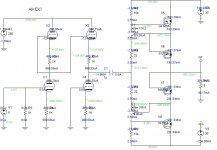
You don't have to use all these tricks at once...
I hope I didn't confuse things by demonstrating
too many unusual things in one drawing...
You probably ought to run the sim to see how
the big nasty electrolytic bypass cap under the
cathode is passing almost no AC. All the bypass
action is on the high quality Loftin White 1uf!
-3db corner frequency for both bypass 4.7Hz
We should now be getting the full value of Mu.
We are down now to a single twin triode for
the full stereo. And no longer have to elevate
heaters to keep top side cathodes safe.
2N5550 might not have wide enough SOA for
this abuse, and MJE15032 is overkill. Maybe
something inbetweenish specwize for Q1?
I forgot, due to Allison fake depletion mode,
Q1 would normally see only 2V VCE, SOA is
fine. Nothing to worry.
Attachments
Last edited:
... just for experiments...
Hi
this is my experiment
when Aikido meets Krill,
only detailed sketch,
worth further imrovment?
Attachments
This is circuit of Counterpoint SA100.
This is not the schematic for either the SA100 or its predecessor, the SA12
Some of the Counterpoint models have a justifiably poor reputation for reliability but not the SA100. It was not a PA amplifier but without abuse it was pretty tough
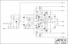
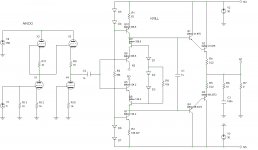
Pawel,
Input drawing lacks PSRR cancellation, its not quite Aikido yet.
I'm doubtful it can swing the necessary current to deal with the
challenge of driving the mosfets fully to the rail. Miller increases
to 1500pF when VGS>VDS according to Cordell. You gonna need
to swing about +/-20mA.
Output drawing 2 is almost pefect, except 4 diodes (rather than 2)
should be square law Schottky. And have about 10ohms strapped
across the diode stack to insure the output devices always try to
conduct a minimum 120mA or so. Never suck the threshold charge
off the gate.
This will give you quasi-complimentary Schottky square law crossing,
rather than law of hot mismatched never quite complement IRF(9)240.
Really thinks like class VischB+CCS rather than AB. But power devices
forced to conduct and cross like perfect AB which is all that matters.
Maybe especially important not to have a crossing distortion where
there is no fallback upon GNF loop to fix the defect.
I'm not in favor the opamp driving those emitters, except as a servo.
I still think the emitters should be capacitively coupled to the tubes
without going through the op-amp.
My drawing wasn't ready, I was having sim trouble with the op-amp
in the servo loop. But looks like cross between your 2nd drawing and
Apex's last posted drawing. I fully draw out Apex's CCS and tried to
keep as many parts same, wherever wasn't critical to new function.
Maybe this weekend I'll show what I had in mind.
Last edited:
Why do you think that (post #1) is not schematic of Counterpoint SA100? Do you have some other schematic of SA100?This is not the schematic for either the SA100 or its predecessor, the SA12
Some of the Counterpoint models have a justifiably poor reputation for reliability but not the SA100. It was not a PA amplifier but without abuse it was pretty tough
Regards
Why do you think that (post #1) is not schematic of Counterpoint SA100? Do you have some other schematic of SA100?
Regards
Because I have the factory manual(s)
Is this service manuals with schematics, would you share, please?Because I have the factory manual(s)
Is this service manuals with schematics, would you share, please?
No, they are copyrighted. If you wish to have the original manuals you are free to contact Mike Elliott (the former Counterpoint designer) at Alta Vista Audio Home Page
Thanks, I don't want anything what is copyrighted, becouse I think the best things are for free.No, they are copyrighted. If you wish to have the original manuals you are free to contact Mike Elliott (the former Counterpoint designer) at Alta Vista Audio Home Page
Regards
Last edited:
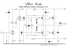
Mosfet/Tube Hybrid Power Amplifier
Hey Apexaudio, you are welcome to try my design (as long as you do not use it for commercial gain). It is really built on a Hafler 200 (or 220) but can easily be modified to run with modern MOSFETs like say Toshiba or Hitachi. Amp-guy asked for off-set, so I added a 10K pot across the BIAS network. This should be adjusted for say +/- 10mV on the output terminal w/ ref to ground (zero volts).
So how does this setup sound? Very tube like. No booming bass, but great vocals and sound stage. It really is a tube amp w/ the output tubes and transformer replaced by a balanced MOSET source follower. To my ears this is a great hybrid approach since it essentially behaves like a 2 X 110 Watt tube amp. I hear detail I never heard before...! - One word of caution: you MUST use good quality parts since this design has zero global loop feedback. Play around w/ different caps and resistors. I found that good old NOS Allen Bradley resistors work well. Kiwame is also OK. You can use Mills WW if you like. This is a great platform to play around w/ parts to get 'real tube sound' from a pair of MOSFETs. - Or the sound that fits your taste.
Cheers,
D.
Attachments
Pawel, Input drawing lacks PSRR cancellation, its not quite Aikido yet...
Kenpeter
I wrote, this is a sketch, everybody knows how Aikido looks like, the simplified sketch was for simulation reason.
You gonna need to swing about +/-20mA
for IRFs yes - for Krill no!
I'm not in favor the opamp driving those emitters, except as a servo.
like before: this is a sketch and a picture with the opamp was only an example how works the buffer with error correction. On the left is a schematic with planned capacitice connection, which I proposed to discuss.
Hi Volfort
can you swing with 6sn7 +-20mA?
Could you add joins on your schematic, i am confused in some points; are they connected or just crossed...
anyway very interested, is it working?
Thank you, but modified for modern fets (bias circuit), adding DC servo and VI limiter... that is already done on my schematics.Hey Apexaudio, you are welcome to try my design (as long as you do not use it for commercial gain). It is really built on a Hafler 200 (or 220) but can easily be modified to run with modern MOSFETs like say Toshiba or Hitachi. Amp-guy asked for off-set, so I added a 10K pot across the BIAS network. This should be adjusted for say +/- 10mV on the output terminal w/ ref to ground (zero volts).
So how does this setup sound? Very tube like. No booming bass, but great vocals and sound stage. It really is a tube amp w/ the output tubes and transformer replaced by a balanced MOSET source follower. To my ears this is a great hybrid approach since it essentially behaves like a 2 X 110 Watt tube amp. I hear detail I never heard before...! - One word of caution: you MUST use good quality parts since this design has zero global loop feedback. Play around w/ different caps and resistors. I found that good old NOS Allen Bradley resistors work well. Kiwame is also OK. You can use Mills WW if you like. This is a great platform to play around w/ parts to get 'real tube sound' from a pair of MOSFETs. - Or the sound that fits your taste.
Cheers,
D.
Regards
I tried and tried to simulate your OP-Amp based servo.
Both as originally drawn, and with every tweak I could
imagine to try and "fix" it... Maybe some other changes
I've made elsewhere were incompatible w this servo?
Tried several LT op-amp models as substitute for TL071
In desperation, I threw a choke at it, and this simpler
DC solution actually seems to simulate out pretty good.
Its probably OK small core saturates in event of need
to correct severe DC offset, something else is wrong!
Probably doesn't demand big gapped parafeed choke.
More o' my circuit bending wierdness to laugh at...
I wanted to sim w. same transistor choice as Apex,
except I havn't collected all the needed models yet.
You are not seeing vertical MOSFET crossing here. You
are seeing cold Schottky Diode. Mismatch of MOSFETs
and output device temperatures have little effect upon
this crossing's shape. VischB + CCS
Smoove crossing!!! But still maybe something wrong
with circuit behavior near rail clipping (above 50V)?
Or maybe thats just LTSpice math acting strange for
no reason? Does that just to make me look stOOpid..
D10+D11 probably not necessary, I just don't trust
choke misbehavior never to reverse VBE.
Attachments
Last edited:
Hi Kenpeter,
what for is L1?
Please describe how to make it in practice,
- Status
- This old topic is closed. If you want to reopen this topic, contact a moderator using the "Report Post" button.
- Home
- Amplifiers
- Solid State
- Tube/Mosfet 100W Hybrid Amplifier