The power amp is a Parasound A21, and works just fine. The preamp is a type 26 DHT, and runs so cool it would also be fine. But the fans were installed when I was using a lot more valves which DID give out a lot of heat.Before I answer that, those fans you installed, what happens when the amp is used without them blowing air?
As I have very little space, and too much equipment, I need to be able to stack the shelves close together. So the fans are now insurance. There are plenty of amps that have internal fans; are they also poorly designed?
But anyway, this is the Tubelab sub forum, so my suggestion was for mkane77g; what I use doesn't matter.
My B+ is running between 324-326 and my B- is between 210-212 (bias is set at 27)....Is this low enough for the 45’s?
My old Lexan amp runs about 320 to 325 volts. The max spec for a 45 is 275 or 300 volts depending on what you read. I have yet to find a maximum plate dissipation spec.
My amp wound up with a pair of NX-483 tubes in it, which are globe 45's with a 5 volt filament. The stickers on them indicate that they were "tested and installed" in 1929, as did all the other tubes that I pulled out of a flea market find old Sparton radio chassis. Those same tubes are still working just fine in my amp. I run the current at about 27 mA per tube, for roughly 10 watts of dissipation. This works for me, but YMMV. I found that these tubes sounded a bit better as I cranked up the voltage, but didn't want to go any higher. My OPT's are Electra Prints that I had made over 10 years ago.
For an off the shelf choice you can take a look at the One Electron UBT-2.
The UBT series have a higher primary DC resistance that most similar OPT's. The UBT-2 is specced at 435 ohms. For a 4800 ohm OPT this means that almost 10% of your output power will be lost in this resistance, as will about 13 volts of DC. The UBT-1 that I had sounded quite nice in a 300B amp, but made the lowest power of any I tried......this was also 10 years ago.
The UBT series have a higher primary DC resistance that most similar OPT's. The UBT-2 is specced at 435 ohms. For a 4800 ohm OPT this means that almost 10% of your output power will be lost in this resistance, as will about 13 volts of DC. The UBT-1 that I had sounded quite nice in a 300B amp, but made the lowest power of any I tried......this was also 10 years ago.
Thank you George for sharing this.
Happy New Year!
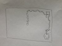
The way you have that wired is a recipe for mains hum. The mains wiring should be a twisted pair. You have a big open loop. Keep the leads to the fuse as short as possible, then twist to the switch, then to the power transformer. Run the twisted pair along the edge of the chassis, then to the PT.
Sheldon
I put the hottest running amp at the top. If not feasible, I put a layer of foil faced foam tape under the shelf above it. Works fine.But the fans were installed when I was using a lot more valves which DID give out a lot of heat.
As I have very little space, and too much equipment, I need to be able to stack the shelves close together. So the fans are now insurance.
They are designed to be stacked on top of each other, i.e. PA amps. Different typology and they are properly designed for the original intents and purposes.There are plenty of amps that have internal fans; are they also poorly designed?
Just commenting on what you posted here.what I use doesn't matter.

The way you have that wired is a recipe for mains hum. The mains wiring should be a twisted pair. You have a big open loop. Keep the leads to the fuse as short as possible, then twist to the switch, then to the power transformer. Run the twisted pair along the edge of the chassis, then to the PT.
Sheldon
Here is a video for some help. https://www.youtube.com/watch?v=enRwrvWKLrA
Sheldon, thanks for that. If you could do a drawing about that I could follow it. If I decipher what your saying I need to move the rocker switch also.
The switch can stay where it is. Just run a twisted pair from the main socket/fuse to the switch and twisted from there to the primary. Twist the leads of the primary too, in the same direction so they don't unwind each other. Take care not to pull hard on the primary wires when you twist them.
Sheldon
You'll also want to twist the heater wiring right up to the sockets. I prefer solid core wire for the twisted pairs, as the rigidity will have them stay where you put them. That's helpful, because you want to maintain as much distance as practical between signal wiring and AC wiring, as the radiated field diminishes as the square of the distance. Also make sure that signal wires cross the AC wiring (90 degrees is optimal, but less is OK), and not run parallel to the AC wiring.
BTW, I twist the output and input wires as well. For input, you can also use small coax. The twisting (or shielding) minimizes AC pickup also. Not a big deal for the output wiring in a non-feedback amp, but makes a neater build IMO.
BTW, I twist the output and input wires as well. For input, you can also use small coax. The twisting (or shielding) minimizes AC pickup also. Not a big deal for the output wiring in a non-feedback amp, but makes a neater build IMO.
Last edited:
This is well worth reading,if you haven't already done so. http://www.diyaudio.com/forums/tubes-valves/211731-heater-wiring-good-bad-ugly.html
Another attempt. Wont power on until it's approved good to go. Wire color not the best. It's all I have.
An externally hosted image should be here but it was not working when we last tested it.
Got that Sheldon. Should I make changes?
Much better. Ideally, the same wire type should be used for each wire of the twisted pair. That makes each wire twist the same, for the best cancellation of the fields. But you've got most of the benefit there. .
Is that loop of orange/white/yellow additional output taps? I'm not sure if that would transmit something back into the secondary. If it were me, and I wanted to save those leads, I'd twist them and move that loop away from the AC power wires. Or, leave them there and flip the B/W pair over to the other side of that loop. Might have no effect, but couldn't hurt.
Sheldon
Last edited:
An externally hosted image should be here but it was not working when we last tested it.
I've been trying the 4 Ohm vs 8 to see which I like best. I use the 4 Ohm on another SET amp we use. seems as if the noise floor is a bit quieter using 4 Ohm tap. The TSE is real quiet and don't think there will be much difference. I have another choke on the way and am trying to decide on a different pair of OPA's.
Last edited:
- Status
- This old topic is closed. If you want to reopen this topic, contact a moderator using the "Report Post" button.
- Home
- More Vendors...
- Tubelab
- TSE & 45's