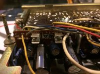
WaFfLe your pic of the schematic helped a lot! How'd you get it to print so clearly? With your advice I made a probe today and checked the output on pin 4 of the big IC. Both sides had signal. Noticed on your schematic that there were two fuses after this. I didn't see these tucked behind the wires. Sure enough one of them is open. If my eyes are seeing right it says V2A on one side and 30C on the other side. Any idea what kind of fuse ratings I need?
What a great community this site is!
What a great community this site is!
the fuses are both the same rating, mine are both good and both produce audio in mono.
if i remember correctly the ratings are printed on the amplifier board.
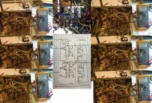
as far as the schematic, i was able to find 1 person who sells the complete service manual online and he was kind enough to blow up the main schematic onto 2 large pages.
im not trying to advertise for the guy i got it from, but because it was extremely difficult for me to locate this information... stereomanuals.com
also, im glad that you are finding my frustrations useful! the main reason i decided to post this thread as i worked through the receiver is the absolute lack of information on the unit on the web.
btw i am by no means an expert at radio restoration so take my info with a grain of salt.
if i remember correctly the ratings are printed on the amplifier board.
as far as the schematic, i was able to find 1 person who sells the complete service manual online and he was kind enough to blow up the main schematic onto 2 large pages.
im not trying to advertise for the guy i got it from, but because it was extremely difficult for me to locate this information... stereomanuals.com
also, im glad that you are finding my frustrations useful! the main reason i decided to post this thread as i worked through the receiver is the absolute lack of information on the unit on the web.
btw i am by no means an expert at radio restoration so take my info with a grain of salt.
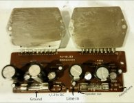
As far as the 2amp fuses on the amp board. Mine has Buss SFE20 which is definitely not a good sign since the board obviously says 2 A, these are 20 A. Which obviously someone has been in here before I was and blew the crap out of the original fuses multiple times.
Attachments
Well it appears that I am losing a large amount of signal through the power/speaker selector. Which is a good sign because I am narrowing down what is causing this massive loss. The signal coming in sounds fantastic however the signal coming out is crap on both channels and one channel is vastly louder than the other
Attachments
Hey Waffle,
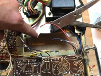
How'd you remove the the card with the bass/treble controls?
I'd like to test the collectors on TR501/502 as Mooly suggested in an earlier thread but having a bear of a time removing it. The Treble pot gets in the way.
I may start desoldering some of the wires to get it off.
How'd you remove the the card with the bass/treble controls?
I'd like to test the collectors on TR501/502 as Mooly suggested in an earlier thread but having a bear of a time removing it. The Treble pot gets in the way.
I may start desoldering some of the wires to get it off.
I found that the stereo select switch is at fault having a bad connection, so I jumped it... still had a quiet channel but not dead like before.
So I traced back to the tone board... looked ok.
Ran line input directly into the amp section...STILL QUIET..... out comes the amp to test on my bench supply.
More to come later.
So I traced back to the tone board... looked ok.
Ran line input directly into the amp section...STILL QUIET..... out comes the amp to test on my bench supply.
More to come later.
Attachments
Waffle! You're a life saver. Checking the "arrows" the DC voltage coming into TR 501 and 502 are different. The point closer to the middle (I think TR501) is measuring 1.55, the other one is measure 1.6!
Also, is there an easy way to test the input selector with the probe. When I trace the aux in to the board the 1kHz tone sounds good. When I press the various leads on the input selector none of them sound quite as loud.
Also, is there an easy way to test the input selector with the probe. When I trace the aux in to the board the 1kHz tone sounds good. When I press the various leads on the input selector none of them sound quite as loud.
Also noticed an out of spec resistor. The one of the 2.2 k resistors from the volume pot is measuring 1.5k. Here's the weird thing. For the record my only experience working with circuits is talking a highschool tech class.
The signal after this out of spec resistor is much quieter. Shouldn't this be the opposite?
Anyhow I'm going to replace the resistor, not sure if this will solve the problem, but interesting. Starting to really enjoy this now.
The signal after this out of spec resistor is much quieter. Shouldn't this be the opposite?
Anyhow I'm going to replace the resistor, not sure if this will solve the problem, but interesting. Starting to really enjoy this now.
Thanks Waffle. I've got a resistor pack on order so it'll be a while before I get it.
Just curious if you can explain how to check TR501/TR502 using my multi meter.
Here's what I'm doing, switch my multimeter to diode mode.
TR 502
Neg on Arrow, Pos on lead next to it (middle I'm assuming) reading = 1
Negative on Arrow Pos on third lead = 610
Positive on Arrow, Neg on lead next to it = 1
Positive on Arrow, Neg on 3rd lead = 1
TR 501
Neg on Arrow, Pos on lead next to it (middle I'm assuming) reading = 1
Negative on Arrow Pos on third lead = 613
Positive on Arrow, Neg on lead next to it = 1
Positive on Arrow, Neg on 3rd lead = 1
I'm assuming the transistors are good.
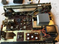
Sorry for the lack of updates. Between work, tube radios, life in general... I made time to get back on this thing.
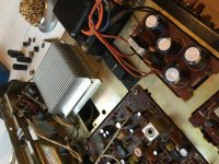
I went ahead with the lm3886 chipamp conversion.
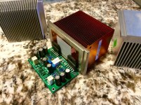
I'm currently finishing the wiring. The transformer conveniently supplies +/-21vdc which is perfect for a decent chip amp!
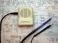
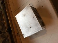
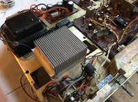
For heat removal I am using an old p4 cup cooler from cooler master. Drilled and tapped 5 holes to accept standard 6-32 thread computer screws. I used my nibbler to open the existing slot for the crapped out toshiba TH9015P "power pack". As of right now. I have steady power even when stress testing the amp with 2 12" car subwoofers in attempt to find voltage drop and temperature rises.
Results from testing is clipping @ 59.9w 1st channel and 60.5w 2nd channel. The thermals rose to a max of 104.5 degrees Fahrenheit. So it seems I'm good to continue!
I went ahead with the lm3886 chipamp conversion.
I'm currently finishing the wiring. The transformer conveniently supplies +/-21vdc which is perfect for a decent chip amp!
For heat removal I am using an old p4 cup cooler from cooler master. Drilled and tapped 5 holes to accept standard 6-32 thread computer screws. I used my nibbler to open the existing slot for the crapped out toshiba TH9015P "power pack". As of right now. I have steady power even when stress testing the amp with 2 12" car subwoofers in attempt to find voltage drop and temperature rises.
Results from testing is clipping @ 59.9w 1st channel and 60.5w 2nd channel. The thermals rose to a max of 104.5 degrees Fahrenheit. So it seems I'm good to continue!
Attachments
Last edited:
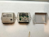
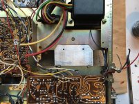
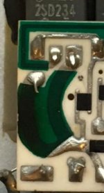
well, I guess you could actually repair the thick film module now you have got it apart... ")
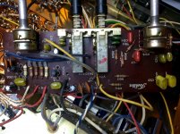
there looks to be a discolouration on the substrate board, an emitter resistor likely cooked. The emitter solder pad also looks dodgy.

there looks to be a discolouration on the substrate board, an emitter resistor likely cooked. The emitter solder pad also looks dodgy.
Attachments
Last edited:
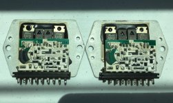
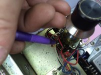
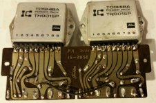
Wow, that is unexpected! I thought the transistor dies would be exposed but here we have totally standard discrete parts! How primitive! This makes repair way easier than most of these pesky things.and for those interested, i went ahead and drilled the rivets on the Toshiba TH9015P to reveal whats going on inside these things.
- Status
- This old topic is closed. If you want to reopen this topic, contact a moderator using the "Report Post" button.
- Home
- Amplifiers
- Solid State
- Toshiba sa-400