Well, it's working ish. Still having issues. Tuner works better than before. Right outputs have basically no sound unless the volume is cranked. Also if I flip the stereo switch. The left output drops to super quiet like the right is doing. It kinda sucks tracing these leads. The main speaker selector has a ton of shielded wires running to it. I have to go through the entire audio path and figure out what has a bad connection
well, i decided to pull this thing back off the shelf and hit it with my signal path tracer, what i discovered is that the tuner and inputs have clear L+R audio and the issue is contained between the small amplifier section and most likely headphone jack. the headphone jack has a muting function that kills audio out so it could well be causing the crusty audio difference...
ill have to look at it later on but at least i know that the pre stage seems to be ok.
the signal tracer is a neat little DIY thing i found online that basically includes a mono radioshack powered speaker, headphone lead and a capacitor to block DC
ill have to look at it later on but at least i know that the pre stage seems to be ok.
the signal tracer is a neat little DIY thing i found online that basically includes a mono radioshack powered speaker, headphone lead and a capacitor to block DC
It was a long a time ago for me, probably around 5 or 6 thousand posts back.
From quickly skimming through it all, I don't think the IC was suspect, at least not if you had audio on both channels (no matter what you had to do to get it).
As mentioned before, a scope is your best friend for faults like this.
From quickly skimming through it all, I don't think the IC was suspect, at least not if you had audio on both channels (no matter what you had to do to get it).
As mentioned before, a scope is your best friend for faults like this.
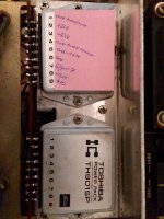
i still am interested in finding any info on the power ic, but it seems there is still no information on these things or even what they could be supplemented with
part# TH9015P
This IC was also used (4 of them) on the quadraphonic Toshiba SB-404 amp. Unlike the early STK IC's, it is a complete amp (differential input, VAS, complementary drivers, quasi-output stage), so it can be replaced by a mono chip amp. I used to have a rather fuzzy datasheet for the TH9013-9015 chips, I see if I can find it...
Timely that I found this post! Sorry to thread jack.
I was given this amp and have similar issues. The MAIN in is the only input that works (volume and other options won't work) and only output from the Left channel.
I'm not sure I'm going to recap. Any easy ways to diagnose this issue? This is my first attempt at restoring an amp.
Let me know if I can help in any way.
I was given this amp and have similar issues. The MAIN in is the only input that works (
Faults like this are usually very easy to diagnose... given the right test equipment.
Feed a suitable input (e.g. sine of 1kHz @ 200 mv rms), into a non functioning set of inputs and trace the signal from that point through the various switches and pots etc.
From the term "main input" you could be talking about a guitar amplifier. Is this the same amplifier as the OP? In any case, Mooly is right since there could be a few paths to the power amplifier and you need to check them all out logically. A common problem in my experience has been dirty contacts on switches - in fact, any signal switches where the contacts just close rather than slide or "wipe" together. The equipment needed is not complicated but a schematic and service manual could be very helpful if not essential.
Most people understand tracing fine but when it comes to probing the various points where signal should be, they are looking about for some sensitive amplifier to hear it. You could just wire up a plug and use the main amp (take care as there is no volume control there), use a PC sound system, headphone amp, radio etc but you also need a probe with a capacitor of say, 100nF in series with the probe lead to isolate it from accidental contact with power sources. There will be a common ground return in a stereo amplifier but if hum is bad, another cap in series with that ground lead might eliminate it. A shielded lead such as a length of mic. cable, guitar lead RCA AV lead etc. is best and I've even used an old probe from a multimeter to test.
Most people understand tracing fine but when it comes to probing the various points where signal should be, they are looking about for some sensitive amplifier to hear it. You could just wire up a plug and use the main amp (take care as there is no volume control there), use a PC sound system, headphone amp, radio etc but you also need a probe with a capacitor of say, 100nF in series with the probe lead to isolate it from accidental contact with power sources. There will be a common ground return in a stereo amplifier but if hum is bad, another cap in series with that ground lead might eliminate it. A shielded lead such as a length of mic. cable, guitar lead RCA AV lead etc. is best and I've even used an old probe from a multimeter to test.
Last edited:
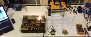
so after running a 1khz sine wave through the amp and finally connecting my pc scope to the output, it appears that the right channel has nothing coming out of it, the only sound it produces is in mono and the audio i was hearing out of the channel appears to be bleeding through from the left channel at high volumes.
-feebz the audio path tracer i made was made from this post > Troubleshooting your amp with audio signal tracing |
and the scope is just a usb behringer soundcard with rca in/out
-feebz the audio path tracer i made was made from this post > Troubleshooting your amp with audio signal tracing |
and the scope is just a usb behringer soundcard with rca in/out
im about to take another stab at this today and hopefully come up with something promising.
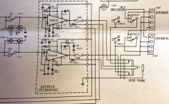
in the meantime, this is what i found with my multi-meter and kinda guessed based on the schematic what pin does what (see attached)
in the meantime, this is what i found with my multi-meter and kinda guessed based on the schematic what pin does what (see attached)
Attachments
Well I found an out of spec resistor on the volume to balance pot. Replaced both and it seemed to fix the signal all the way through the tone control board into the amplifier. Still have sht coming out of one channel but the good one cleared up a little. Then I realized I had it in mono. Switched to stereo and the channel died. Guess I'll have to look again later to find where the signal stops
- Status
- This old topic is closed. If you want to reopen this topic, contact a moderator using the "Report Post" button.
- Home
- Amplifiers
- Solid State
- Toshiba sa-400