Your omitting of the first resistor and using the same R value for all remaining segments is fine.
However, R = 80.66 Kohms sounds too low.
Can you post what values you used for inputs #1 thru #6 in the spreadsheet?
Like SyBorg I use 2W metal film or metal oxide resistors, using multiple in series when necessary to stay within the recommended working voltage. We can calculate/plot those for you once a value for R has been determined.
Your omitting of the first resistor and using the same R value for all remaining segments is fine.
However, R = 80.66 Kohms sounds too low.
Can you post what values you used for inputs #1 thru #6 in the spreadsheet?
Like SyBorg I use 2W metal film or metal oxide resistors, using multiple in series when necessary to stay within the recommended working voltage. We can calculate/plot those for you once a value for R has been determined.
My panels will be 12 x 48 with active radiating area of 10.5 x 46.5"; however, the rods will be 47.75 long and extend under the spacers on the top and bottom; hence, 47.75" contributing to capacitance. The stators will use 134 vertical wires arranged in (11) groups of 13,12,12,12,12,12,12,12,12,12,13 wires. This will be a bi-amped design with the panel crossing over to a woofer at 220Hz using a 24db or 48db filter slope.
Spread sheet inputs 1-6 are:
1 > 47.5"
2 > 10.5"
3 > 0.0625"
4 > 3.5 M
5 > 11
6 > 200 Hz
Giving: C/section = 81.97 pF
R/section = 80.24 Kohms
Last edited:
aaaAaah…ok. You incorrectly used 11 segments in the spreadsheet since you plan to have 11 physical segments. Remember for a symmetrically segmented ESL, the number of electrical segments = (number of physical segments + 1)/2. I attempted to clarify this back in post#79
http://www.diyaudio.com/forums/plan...-segmented-wire-stator-esl-8.html#post4192217
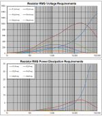
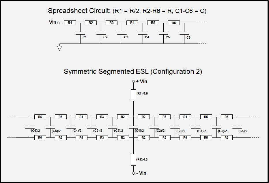
For your 11 physical segments you should be modeling with 6 electrical segments in the spreadsheet. The top figure in the Attachment #1 shows what the spreadsheet is using to model the on-axis response shown in the plot. Each of the segments has the same size/capacitance = C shown in the spreadsheet. Each of the resistors has the same value = R shown in the spreadsheet except the first, R1 is half of R.
Now, if you want to place these 6 electrical segments into a symmetrical configuration to improve polar response you start by placing the first segment in the middle. Then you take the second segment, split it in half, and place each half on either side of the middle segment. Next take the third segment, split it in half, and place each half to the outside of the second segments halves. Etc…
To further improve dispersion, you can cut the size of the center segment in half so it is the same size as the outer physical segment portions. Since you have reduced the area of the center segment, the HF response would droop if no other changes were made. To keep flat on axis response, you can adjust the value of the resistors feeding the center segment down. This is Configuration 2.
In your case, with N=6 & fL=200Hz, R= 147Kohm; with fL=220Hz, R= 133.7Kohm.
With 40Vrms input and 1:75 step-up ratio, the worst case RMS voltage and power dissipation requirements for the resistors are shown in Attachment #2. Remember you don’t need to consider R1 since you are moving that to the primary side. Obviously music does not contain continuous HF tones, so these values are rather conservative. If it was me, I would probably use two 68K/2W resistors in series between each segment. If you plan to do a lot of high SPL testing, you might consider three 47K/2W resistors in series.
http://www.diyaudio.com/forums/plan...-segmented-wire-stator-esl-8.html#post4192217
For your 11 physical segments you should be modeling with 6 electrical segments in the spreadsheet. The top figure in the Attachment #1 shows what the spreadsheet is using to model the on-axis response shown in the plot. Each of the segments has the same size/capacitance = C shown in the spreadsheet. Each of the resistors has the same value = R shown in the spreadsheet except the first, R1 is half of R.
Now, if you want to place these 6 electrical segments into a symmetrical configuration to improve polar response you start by placing the first segment in the middle. Then you take the second segment, split it in half, and place each half on either side of the middle segment. Next take the third segment, split it in half, and place each half to the outside of the second segments halves. Etc…
To further improve dispersion, you can cut the size of the center segment in half so it is the same size as the outer physical segment portions. Since you have reduced the area of the center segment, the HF response would droop if no other changes were made. To keep flat on axis response, you can adjust the value of the resistors feeding the center segment down. This is Configuration 2.
In your case, with N=6 & fL=200Hz, R= 147Kohm; with fL=220Hz, R= 133.7Kohm.
With 40Vrms input and 1:75 step-up ratio, the worst case RMS voltage and power dissipation requirements for the resistors are shown in Attachment #2. Remember you don’t need to consider R1 since you are moving that to the primary side. Obviously music does not contain continuous HF tones, so these values are rather conservative. If it was me, I would probably use two 68K/2W resistors in series between each segment. If you plan to do a lot of high SPL testing, you might consider three 47K/2W resistors in series.
Attachments

Thanks Steve,
I'm a little depressed right now over having started this project without a firm understanding of the requirements. Especially since I've already spliced and glued the rods to the egg crates on two of the four stators. So now I'm stopped... having to rethink whether the (11) physical segments / (6) electrical segments sufficient.
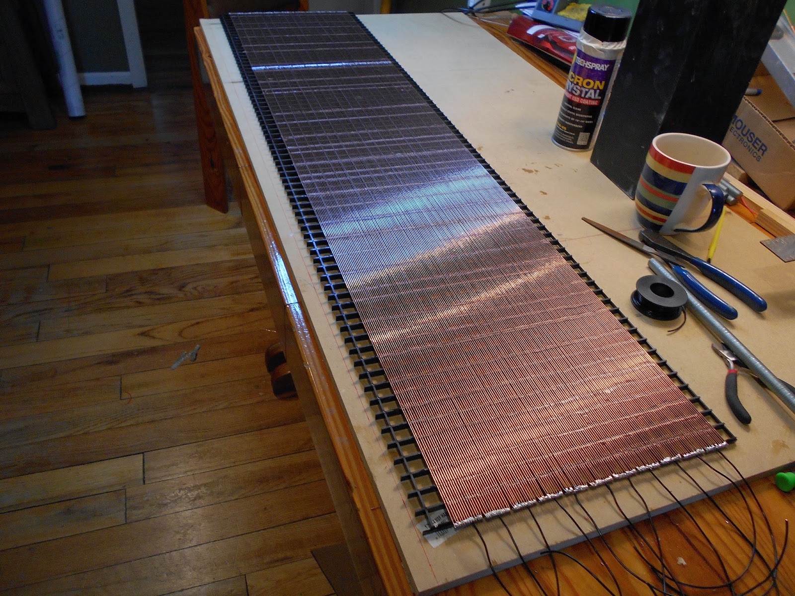
I had to splice the 36" rods to make them 48" long. And I soldered up the wire groups before transferring them to the plastic egg crate.
And while it would be easy to reconfigure the wire groups at the ends where the leads attach, it would not be easy to desolder and re-configure the connections in the middle of the panel where the rod groups are spliced directly over one of the plastic vanes in the egg crate.
Note the splice line at about 3/4 height of the panel. The 12 wires in each group are cross-connected there and one of the panel's horizontal spacers will be centered over the splice line.
I now understand clearly the difference between electrical and physical sections, but I'm still trying to figure out how the sketch below is equivalent to the configuration 2 sketch in the spread sheet-- specifically, why the R value in the idealized upper schematic isn't 2R as shown in the spread sheet.
(I'm working from memory here since I'm at home right now without and I can only open the spread sheet on my work computer)
I'm a little depressed right now over having started this project without a firm understanding of the requirements. Especially since I've already spliced and glued the rods to the egg crates on two of the four stators. So now I'm stopped... having to rethink whether the (11) physical segments / (6) electrical segments sufficient.
I had to splice the 36" rods to make them 48" long. And I soldered up the wire groups before transferring them to the plastic egg crate.
And while it would be easy to reconfigure the wire groups at the ends where the leads attach, it would not be easy to desolder and re-configure the connections in the middle of the panel where the rod groups are spliced directly over one of the plastic vanes in the egg crate.
Note the splice line at about 3/4 height of the panel. The 12 wires in each group are cross-connected there and one of the panel's horizontal spacers will be centered over the splice line.
I now understand clearly the difference between electrical and physical sections, but I'm still trying to figure out how the sketch below is equivalent to the configuration 2 sketch in the spread sheet-- specifically, why the R value in the idealized upper schematic isn't 2R as shown in the spread sheet.
(I'm working from memory here since I'm at home right now without and I can only open the spread sheet on my work computer)
Last edited:
I think you are just fine as is. You will not be disappointed with the dispersion.I'm a little depressed right now …having to rethink whether the (11) physical segments / (6) electrical segments sufficient.
Remember Configuration 2 with (6) electrical segments is nearly equivalent dispersion-wise to Configuration 1 with (12).
Configuration 1 is what the AES paper design formulas and my rule of thumb are based on.
I now understand clearly the difference between electrical and physical sections, but I'm still trying to figure out how the sketch below is equivalent to the configuration 2 sketch in the spread sheet-- specifically, why the R value in the idealized upper schematic isn't 2R as shown in the spread sheet.
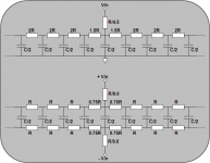
The 2R value you are thinking of is if you only segment one of the stators.(top pic)
In practice dispersion is improved if you segment both stators(bottom pic) even though theoretically there should be no difference.
This is the "standard" segmented stator configuration that most people use.
Basically, going from top pic to bottom pic, you are moving on of the 2Rs to the other stator.
It is a series connection of 2R & C/2, so it is electrically equivalent with one R on either side of C/2 or 2R on just one side.
Attachments
Looks impressive and neatly executed.
After some delay I am ready to start some testing myself and appreciate advise from you experienced guys.
What is latest opinion for the best material for the membrane and what thickness.
Apart from a construction and segmentation point of view, is there any advantage for a wire stator or a perforated stator?
Why is the music signal put on the stators instead of the membrane, what are the pro's and con's?
What resonance frequency are we aiming for if we want “low” frequencies too?
Can a wide frequency range ESL ( 250Hz -30kHz) be made without separate high and low segments and have a decent sound pressure?
Edmund
Hi Edmund
"What is latest opinion for the best material for the membrane and what thickness?"
In isolation, the acoustic output of the membrane has a first order low-pass response with a cut-off frequency given by ~100 kHz/thickness in microns. So a 3.5 um diaphragm has a cut off about 28 kHz, a 6 um diaphragm about 16 kHz.
"Apart from a construction and segmentation point of view, is there any advantage for a wire stator or a perforated stator?"
I've not built a wire stator ESL so others may be better able to advise. However, the wire stator has the advantage of easy electrical segmentation which enables passive equalisation and better polar response. Perforated metal plate does not allow this easily, perforated PCB does.
"Why is the music signal put on the stators instead of the membrane, what are the pro's and con's?"
ESLs exhibit the lowest distortion when the charge on the diaphragm is not allowed to move about (constant charge operation). This is not possible with the audio applied to the diaphragm, which would be a form of constant voltage operation. Some commercial ESL operate this way because the acoustic output can be made larger.
"What resonance frequency are we aiming for if we want “low” frequencies too?"
That depends. For a full range ESL, the resonant frequency is used to extend the bass response in the same way as the Helmholtz resonance is used in Bass-reflex cabinets. For this purpose the resonance would normally be below 100 Hz, perhaps below 50 Hz. Depends how low you want to go. The penalty for low resonant frequency is large diaphragm displacements.
"Can a wide frequency range ESL ( 250Hz -30kHz) be made without separate high and low segments and have a decent sound pressure?"
Yes, but you are right, max SPL and sensitivity suffer. The maximum output from an ESL more or less depends only on area of the panel and low cut- off frequency - actually by how much bass you can produce - higher frequencies are always easier. If you use some of the panel area for tweeter/midrange say, then there is less area for low frequency SPL.
best wishes
Rod
Hi,
In practical terms, 6u membrane is a good choice between strength, long-term stability, and high frequency response. Of course thinner is possible but then long-term stability is harder to achieve, depending on membrane stretching techniques and overall design of the ESL.
Regards,
Lukas.
What is latest opinion for the best material for the membrane and what thickness.
In practical terms, 6u membrane is a good choice between strength, long-term stability, and high frequency response. Of course thinner is possible but then long-term stability is harder to achieve, depending on membrane stretching techniques and overall design of the ESL.
Yes there is. Reliability. It is way less prone to arching and can withstand higher drive voltages without problems. In case of perforated metal, even coated well(which is very difficult to do) electrical field strength is concentrated around edges of perforations. Typically, at those spots insulation is thinner. Rounded shape of wires solves these problems.Apart from a construction and segmentation point of view, is there any advantage for a wire stator or a perforated stator?
Regards,
Lukas.
Last edited:
Hallo golfnut,
do you know that math behind this?
Can a thicker membrane be "compensated/equalized" to produce far above
16kHz?
"Apart from a construction and segmentation point of view, is there any advantage for a wire stator or a perforated stator?"
I've not built a wire stator ESL so others may be better able to advise. However, the wire stator has the advantage of easy electrical segmentation which enables passive equalization and better polar response. Perforated metal plate does not allow this easily, perforated PCB does.
"Why is the music signal put on the stators instead of the membrane, what are the pro's and con's?"
Oh I am afraid I don't know much about electronics but I would think it is relative and it wouldn't make any difference.
Guess I have a lot to study..
"What resonance frequency are we aiming for if we want “low” frequencies too?"
If possible I want to avoid all kind of resonances because it kills the impulse
response. For the lower low end I don't want an ESL or any other kind of open planar.
"Can a wide frequency range ESL ( 250Hz -30kHz) be made without separate high and low segments and have a decent sound pressure?"
If there is nothing against a one large membrane for "all" frequencies why bother with separating in a high and mid/low segment with all additional problems like filtering.
best wishes
Rod[/QUOTE]
Thanks
Edmund
Great do I understand it right that 3.5 um can go to around 28kHz andHi Edmund
"What is latest opinion for the best material for the membrane and what thickness?"
In isolation, the acoustic output of the membrane has a first order low-pass response with a cut-off frequency given by ~100 kHz/thickness in microns. So a 3.5 um diaphragm has a cut off about 28 kHz, a 6 um diaphragm about 16 kHz.
do you know that math behind this?
Can a thicker membrane be "compensated/equalized" to produce far above
16kHz?
"Apart from a construction and segmentation point of view, is there any advantage for a wire stator or a perforated stator?"
I've not built a wire stator ESL so others may be better able to advise. However, the wire stator has the advantage of easy electrical segmentation which enables passive equalization and better polar response. Perforated metal plate does not allow this easily, perforated PCB does.
"Why is the music signal put on the stators instead of the membrane, what are the pro's and con's?"
ESLs exhibit the lowest distortion when the charge on the diaphragm is not allowed to move about (constant charge operation). This is not possible with the audio applied to the diaphragm, which would be a form of constant voltage operation. Some commercial ESL operate this way because the acoustic output can be made larger.
Oh I am afraid I don't know much about electronics but I would think it is relative and it wouldn't make any difference.
Guess I have a lot to study..
"What resonance frequency are we aiming for if we want “low” frequencies too?"
That depends. For a full range ESL, the resonant frequency is used to extend the bass response in the same way as the Helmholtz resonance is used in Bass-reflex cabinets. For this purpose the resonance would normally be below 100 Hz, perhaps below 50 Hz. Depends how low you want to go. The penalty for low resonant frequency is large diaphragm displacements.
If possible I want to avoid all kind of resonances because it kills the impulse
response. For the lower low end I don't want an ESL or any other kind of open planar.
"Can a wide frequency range ESL ( 250Hz -30kHz) be made without separate high and low segments and have a decent sound pressure?"
Yes, but you are right, max SPL and sensitivity suffer. The maximum output from an ESL more or less depends only on area of the panel and low cut- off frequency - actually by how much bass you can produce - higher frequencies are always easier. If you use some of the panel area for tweeter/midrange say, then there is less area for low frequency SPL.
If there is nothing against a one large membrane for "all" frequencies why bother with separating in a high and mid/low segment with all additional problems like filtering.
best wishes
Rod[/QUOTE]
Thanks
Edmund
"If there is nothing against a one large membrane for "all" frequencies why bother with separating in a high and mid/low segment with all additional problems like filtering."
The answer to that question is "Dispersion" vs "Beaming" and can be found here,
http://www.diyaudio.com/forums/planars-exotics/267826-first-els-info.html#post4182605
jer")
The answer to that question is "Dispersion" vs "Beaming" and can be found here,
http://www.diyaudio.com/forums/planars-exotics/267826-first-els-info.html#post4182605
jer
Hi,
In practical terms, 6u membrane is a good choice between strength, long-term stability, and high frequency response. Of course thinner is possible but then long-term stability is harder to achieve, depending on membrane stretching techniques and overall design of the ESL.
Yes there is. Reliability. It is way less prone to arching and can withstand higher drive voltages without problems. In case of perforated metal, even coated well(which is very difficult to do) electrical field strength is concentrated around edges of perforations. Typically, at those spots insulation is thinner. Rounded shape of wires solves these problems.
Regards,
Lukas.
Good point.
Thanks
Edmund
"If there is nothing against a one large membrane for "all" frequencies why bother with separating in a high and mid/low segment with all additional problems like filtering."
The answer to that question is "Dispersion" vs "Beaming" and can be found here,
http://www.diyaudio.com/forums/planars-exotics/267826-first-els-info.html#post4182605
jer
Hi Jer,
I am well aware of the beaming effect and like to look at that later.
To get started I first want to look at ESL's Magnetostat's and AMT's.
Regards
Edmund
Great do I understand it right that 3.5 um can go to around 28kHz and do you know that math behind this?
Can a thicker membrane be "compensated/equalized" to produce far above 16kHz?Edmund
Yes. Maths is in most acoustics texts – look up the transmittance of a membrane (by reciprocity arguments ESL output is the same). However, (I did say ‘in isolation’) the problem is very much messier than that. There are also effects with the air movement through the stator holes and reflections between the surfaces of the stator, diaphragm damping cloths, dustcovers etc.
A few years ago, I did see a magazine review of one of these ESLs that showed 8% distortion at full power and low frequencies. I imagine that the midrange clarity etc of ESL would be largely intact, and the distortion would be audible only if they are being run flat out."Why is the music signal put on the stators instead of the membrane, what are the pro's and con's?"
Oh I am afraid I don't know much about electronics but I would think it is relative and it wouldn't make any difference.
Edmund
You should not see the low frequency resonance as a negative feature. In some respects the resonant frequency is just a parameter in a mathematical model characterising the low cut-off frequency of the ESL – and in this sense every ESL has one. What’s important is the absence of high-Q resonancesIf possible I want to avoid all kind of resonances because it kills the impulse
response. For the lower low end I don't want an ESL or any other kind of open planar.
Edmund
"Can a wide frequency range ESL ( 250Hz -30kHz) be made without separate high and low segments and have a decent sound pressure?"
If there is nothing against a one large membrane for "all" frequencies why bother with separating in a high and mid/low segment with all additional problems like filtering.
Edmund
Exactly!
best wishes, Rod
I can vouch for the 16 KHz issue with 6um Mylar. My newly made ESLs have rolloff right around 16khz. The rolloff is actually quite steep.
The good news is that I have corrected it via PEQ (I am using the Minidsp PWR-ICE250 for my hybrid floorstanders) and the results are fantastic. I would recommend a decent Mic and REW to measure allow for proper correction.
The good news is that I have corrected it via PEQ (I am using the Minidsp PWR-ICE250 for my hybrid floorstanders) and the results are fantastic. I would recommend a decent Mic and REW to measure allow for proper correction.
- Status
- This old topic is closed. If you want to reopen this topic, contact a moderator using the "Report Post" button.
- Home
- Loudspeakers
- Planars & Exotics
- Thinking about a segmented wire stator ESL