For those of us in N,America this converts to approx 20 AWG for large panels and 22AWG for smaller panels.
Perhaps you would also share what method you use to achieve accurate spacing. Do you use these with lighting grid (egg crate louvers) or some other framework.
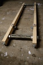
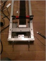
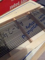
Usually stretched wire stators are glued to a framework rather than light louvers. (pic #1)
Concerning crossbar spacing:
It is important to consider crossbar spacing when selecting wire size.
The thicker the wire, the further apart you can space the crossbars. Here are some recommendations based on building experience:
22 AWG, Crossbar spacing = 2” max
20 AWG, Crossbar spacing = 3” max
18 AWG, Crossbar spacing = 4” max
These spacing recommendations assume that you stretch the wires to strengthen(cold work) and straighten them,
and then release most of the residual tension before gluing wires to crossbars.
Work hardening - Wikipedia, the free encyclopedia
Concerning spacing & stretching of wires:
The two most common methods of spacing the wires is with threaded rods, or pins.
Bazukaz has posted a few pictures of his wire stretching jigs using threaded rods. Wire spacing is determined by thread pitch.
Two pics attached below, and a few links with additional jig pics(both rod & pin):
http://www.diyaudio.com/forums/planars-exotics/96020-esl-welding-rod-stators.html#post1134067
http://www.diyaudio.com/forums/plan...vre-panel-solvent-acoustat-2.html#post3722626
http://www.diyaudio.com/forums/plan...nel-efficiency-first-build-4.html#post3403359
http://www.diyaudio.com/forums/plan...stators-plastic-like-esl-57s.html#post3375308
http://www.diyaudio.com/forums/planars-exotics/71171-wire-stator-gluing-method-11.html#post3717541
http://www.diyaudio.com/forums/plan...sl-project-file-translated-5.html#post2249055
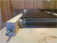
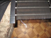
I chose to use pins rather than threaded rods so that I can have more control over the layout, adjacent wires are already attached to each other(no tedious soldering required), and I can include longer lead-out wires for connecting the segmentation resistors. Wire spacing is determined by pin spacing and pin diameter. Dowel pins work great for this application as they are strong and come in a range of diameters. Pics attached below show one of my pin stretchers before and after loading, and one from Wrinex.
If I remember correctly, it took about 30 lbs of force to stretch a single 22AWG wire, 50lbs for 20AWG. So, if your panel has 80 wires and you want to stretch them all at once the stretching jig will need to withstand 2,400 lbs of force for 22AWG and 4,000 lbs of force for 20AWG. The end blocks or threaded rods holding the ends of the wire will need to handle the force too. Each pin needs to handle the force for stretching 2 wires.
It takes a bit of time and thought to construct the jig. But once completed, it takes less than 15 minutes to string the wire between pins, stretch them, and have a perfectly insulated wire stator element ready for gluing to the stator frame crossbars.
When purchasing wire, I agree with Bazukaz that single strand (ie solid core) black PVC hookup wire is the way to go. I prefer crosslinked PVC insulation as it is a bit more resistant to physical damage from nicks or abrasions. Also, it doesn’t shrink back much at all when soldering.
Attachments
Last edited:
Hi Lukas, Jer and Bolserst
Your recommendation of using PVC Coated Wires for Stators is well taken. It is definitely much safer.
I have a few specific questions.
1. Considering the high strains and narrow turning radii involved, would it mot be better to use multi-strand wire instead of single core ?
2. With the entire Panel being wired with a single Conductor, are the individual segments created by cutting the wires at appropriate number of turns ?
Jayant
Hi,
The idea behind using single core wire is to stretch it to plastic deformation zone. It then becomes extremely straight, and, depending on alloy and stresses applied, cold-hardened. Stranded wire is much more flexible , which is not a desirable characteristic at all.
Now if you take a look to photos bolserst have posted, two ways of building a wire streching machine are shown. The first one is by using threaded rods, one type of this kind I can comment in more detail. The operation is as follows :
a) Two stators are placed within wire strethcing jig and fixed there.
b) Wires are wrapped over both stators at once(so you end up with two stators sandwitched between wires). Then stretched to approx 2%.
c) Then wires are released so there is just enough tension to keep them straight
d) Glued or encapsulated to cross bars, depending on materials used. Both stators must be done at this step.
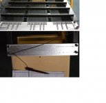
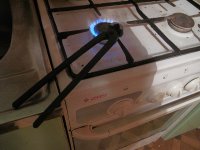
e) Wires are cut, and insulation cleaned from ends. Some pics attached how insulation could be cleaned by using hot pliers from lots of wires with ease. While the method looks crude, results can be surprisingly good.
f) Finally, top/bottom spacers can be fixed to ends of panel
g) Ends of wires are soldered as required by segmentation
Later I have started to use a different type of jig, which uses threaded rods as a guide for wires and special hooks to make zig-zag routing possible. It's somewhat different but also has similarities to both types that were described in previous post by bolserst.
Regards,
Lukas.
The idea behind using single core wire is to stretch it to plastic deformation zone. It then becomes extremely straight, and, depending on alloy and stresses applied, cold-hardened. Stranded wire is much more flexible , which is not a desirable characteristic at all.
Now if you take a look to photos bolserst have posted, two ways of building a wire streching machine are shown. The first one is by using threaded rods, one type of this kind I can comment in more detail. The operation is as follows :
a) Two stators are placed within wire strethcing jig and fixed there.
b) Wires are wrapped over both stators at once(so you end up with two stators sandwitched between wires). Then stretched to approx 2%.
c) Then wires are released so there is just enough tension to keep them straight
d) Glued or encapsulated to cross bars, depending on materials used. Both stators must be done at this step.
e) Wires are cut, and insulation cleaned from ends. Some pics attached how insulation could be cleaned by using hot pliers from lots of wires with ease. While the method looks crude, results can be surprisingly good.
f) Finally, top/bottom spacers can be fixed to ends of panel
g) Ends of wires are soldered as required by segmentation
Later I have started to use a different type of jig, which uses threaded rods as a guide for wires and special hooks to make zig-zag routing possible. It's somewhat different but also has similarities to both types that were described in previous post by bolserst.
Regards,
Lukas.
Attachments

Hi all!
I am back home now after a two week trip to the US.
During this trip, I had a memorable experience listening to Charlie’s Speakers in Savanah. My travel plans took me through Savanah and Charlie was more than accommodating. A gracious host that he is, he also took us through a tour of that beautiful historic City and we spent the evening talking, sharing and listening to music. We also discovered that besides Speakers, some of our other unusual reading interests too turned out to be common !


My previous experience in listening to Electrostatic Speakers is rather limited. On one occasion, I heard ML Speakers which felt rather wimpy - may be on account that they happened to be just unbundled and the sitting position wasn’t exactly optimal. On another occasion, I heard an entry level model of Cadence Audio of India which was enjoyable.
Charlie’s Speakers are bigger than either of the above with a much lower cross over to electrostat Panel from the Dynamic woofer. I was floored the moment first notes were played and never recovered from it for the rest of the evening. The Speakers played loud, crystal clear and with great imaging. Charlie said that on some tracks, he has heard even the sound of shuffling of feet that could have got recorded when someone may have tiptoed across ! The System is definitely that resolving and faithful to the signals. Though one knows that the line source level does not vary sharply in the intensity with changing distances, from the Speakers, to experience that was something. If I had to describe the music heard that heady evening, I would say it was like experiencing a drink with the punch of a good single malt whisky and gentle bouquet of delicately flavored wine – at the same time !
At the parting time, Charlie was most generous with the gift of his copy of “ Electrostatic Loudspeaker Design Cookbook “ by Sanders. This was particularly so since it is now out of print and difficult to come by. Thank You Charlie !
I left Savanah with a resolve to build a pair of Electrostatic Speakers of my own.
Jayant


Hi Jayant,
Thanks for sharing, I enjoyed your post and listening experiences very much! Did you get a chance to hear the difference, via Charlie's switching arrangement, to the differences between the segmented and non-segmented panel? Your thoughts on that especially would be helpful to me as I gather parts to build my own. Thanks, Neil
Hi Neil,
I believe Charlie now prefers to leave his Speakers on Segmented configuartion, having decided it to be better. To compare the two was on my mind but there was so much going on during those few hours and I wanted to leave early as Charlie begins his work very early in the morning, we never got around to it.
I now prefer the segmented design over non-segmented or Curved Panel. Good Luck and look forward to your build.
Jayant
2. With the entire Panel being wired with a single Conductor, are the individual segments created by cutting the wires at appropriate number of turns ?
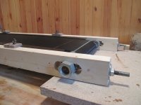
Yes, that is correct. In the panel I wound in Pic#4 from Post#221 above you can see I positioned the pins further back for the wires I was going to cut for the segments. This made it so I could hook up directly to the ladder resistors without needing to solder in additional wire extensions.
You can see my prototype resistor board in upper right of first pic here:
http://www.diyaudio.com/forums/planars-exotics/245454-glue-wire-stators-3.html#post3708397
Hi,
The idea behind using single core wire is to stretch it to plastic deformation zone. It then becomes extremely straight, and, depending on alloy and stresses applied, cold-hardened. Stranded wire is much more flexible , which is not a desirable characteristic at all.
Now if you take a look to photos bolserst have posted, two ways of building a wire streching machine are shown. The first one is by using threaded rods, one type of this kind I can comment in more detail. The operation is as follows :
a) Two stators are placed within wire strethcing jig and fixed there.
b) Wires are wrapped over both stators at once(so you end up with two stators sandwitched between wires). Then stretched to approx 2%.
c) Then wires are released so there is just enough tension to keep them straight
d) Glued or encapsulated to cross bars, depending on materials used. Both stators must be done at this step.
e) Wires are cut, and insulation cleaned from ends. Some pics attached how insulation could be cleaned by using hot pliers from lots of wires with ease. While the method looks crude, results can be surprisingly good.
f) Finally, top/bottom spacers can be fixed to ends of panel
g) Ends of wires are soldered as required by segmentation
Later I have started to use a different type of jig, which uses threaded rods as a guide for wires and special hooks to make zig-zag routing possible. It's somewhat different but also has similarities to both types that were described in previous post by bolserst.
Regards,
Lukas.
Great work Lukas,
This looks much easier than welding rods; especially for taller panels.
Do you happen to know where one could find cheap PVC coated wire in the US?
Hi,
look for H07-VU and H05-VU. That are the names given over here.
H07-VU is The standard wire, the workhorse. You find it in every DIY shop.
As a 3-stranded cable its used throughout the whole House for lighting and electrical supply.
H05-VU is just the little brother.
take care that the suffix is an U, as this marks the solid core wire, while other suffices are for stranded variants.
Just get Yourself a DS and compare to the american stuff.
I'm quite sure that companies like Belden manufacture an equivalent.
jauu
Calvin
I posted a few sources for PVC wire in the US a while back:Do you happen to know where one could find cheap PVC coated wire in the US?
http://www.diyaudio.com/forums/plan...sl-project-file-translated-4.html#post2247842
The last time I purchased wire, I found Jaguar to be significantly cheaper than the others.
They don't have prices posted on their website, but responded quickly to emails and phone calls.
If memory serves...I purchased Type C-PVC.
Well been some time now............any updates?? panels working good..........good bad...big small............thanks
I've been listening to them for a while now and the diaphragms are settled in and panels are working great, no arcing issues, and they are sounding excellent too. I find now that I actually prefer the wide mode most of the time.
I'm not crazy about the esthetics of the platic grids though, even though I think mine look better than most-- I keep the grills on most of the time so that's not really bothersome.
I'm wanting to design another segmented speaker using PVC insulated solid wire and horizontal wooden slat supports rather than plastic grids--- something more esthetically pleasing. I have some nice quarter-sawn oak to play with.
Jazz
I have to say I'm pretty happy with how the full range segmented build turned out. I'm still fiddling with the silk screen fabric to dampen the resonance, but overall ... very smooth. I will have to add a subwoofer eventually as the response really falls off below about 45 Hz, but even without the sub, the sound quality is quite satisfying. Many friends have listened and were amazed, but that is the great sound of ESL for you.
Sounds like fun and should fit in well (aesthetically) with your existing ESL frame and TLine enclosure.I'm wanting to design another segmented speaker using PVC insulated solid wire and horizontal wooden slat supports rather than plastic grids--- something more esthetically pleasing.
I often build test panels out of 5-layer 1/8"(3mm) birch plywood as it is easy to work with and readily available locally when I need a quick build. The only drawback I have found is that on larger panels, there is noticeable leakage current drawn from the HV supply, especially on humid days. I haven't tested it, but I think if only the crossbars are made from wood, and the spacers/perimeter mounting strips are made from better insulating materials, the leakage issue would go away.
Attachments
Bolserst, I used plastisized wood for my cross bars, the bars I made were 1/4" sq about 11" long, each bar had 80 holes drilled into it to secure the rods, these were done in a jig. Because of the amount that had to be drilled, I sat them at 16" centre's, but I found that on lower bass they started ringing, I'm in a dry climate, and it seemed to work fine. Also I made the stators removable by clamping the 3 units together, the DS is about .090 which made it easier to work with, I'm thinking about drilling more cross supports to set at 8" centre's, hopefully this will take care of the ringing. Any ideas or thoughts on this?
Al
Al
Last edited:
Sounds like fun and should fit in well (aesthetically) with your existing ESL frame and TLine enclosure.
I often build test panels out of 5-layer 1/8"(3mm) birch plywood as it is easy to work with and readily available locally when I need a quick build. The only drawback I have found is that on larger panels, there is noticeable leakage current drawn from the HV supply, especially on humid days. I haven't tested it, but I think if only the crossbars are made from wood, and the spacers/perimeter mounting strips are made from better insulating materials, the leakage issue would go away.
That's good to know, thank you.
I'm wondering whether the leak path was from off the diaphragm into the crossbars and from there to the perimeter mounting strips-- or from the periphery of the diaphragm into the perimeter mounting strips.
Questions:
1) Did you attach the diaphragm to the perimeter strips using double-sided tape, and if so, what thickness tape?
2) Did you use a copper foil charge ring mounted on the spacer (tape?)
Jazz
When you use the word “ringing” I think higher frequency, but you mention the ringing occurs when you play bass.I used plastisized wood for my cross bars…at 16" centre's, but I found that on lower bass they started ringing, I'm in a dry climate, and it seemed to work fine… I'm thinking about drilling more cross supports to set at 8" centre's, hopefully this will take care of the ringing. Any ideas or thoughts on this?
Do you hear the ringing when you gently strum your thumb nail across the wires?
I think you are on the right track with the idea of adding more supports, 16” between crossbars is unusually large. One other option is to attach a rubber damping strip diagonally (ie top left to lower right) across each section of unsupported wires. This will minimize the ringing by distributing the resonance frequencies so adjacent wires aren’t humming the same tune. The above mentioned thumb nail test will give you a quick feel for how well it works, comparing one section with damping strip .vs. one without. I have seen this technique used on heat sink fins and some ESL stators (Dayton Wright?).
I believe the leakage path is from the perimeter of the diaphragm to the mounting strip. I generally use a copper tape charge ring and mount the diaphragm with a 2 - 5μm thick layer of acrylic adhesive, the same adhesive used on the 3M foam tapes that are commonly used for spacers in ESLs built with perforated sheet metal stators.I'm wondering whether the leak path was from off the diaphragm into the crossbars and from there to the perimeter mounting strips-- or from the periphery of the diaphragm into the perimeter mounting strips.
From the standpoint of bias leakage currents, you could consider the PVC wire/wood crossbar stators to be fairly conductive, like a perforated sheet metal stator. So, the only insulation between the charge ring and the stators is the spacer and the adhesive. 3M Foam tapes are excellent insulators, wood and acrylic adhesive not so much. One idea I had to disrupt the leakage path to the wood perimeter strips and spacers was to simply put down a thin insulation layer on them(ie Mylar transformer tape) before attaching the diaphragm/charge ring and assembling the halves together…just never got around to trying it.
One other concern with wood is dimensional stability during changing humidity, which directly affects your diaphragm tension.
This is much more of a concern with, say, MDF than hard woods like oak.
- Status
- This old topic is closed. If you want to reopen this topic, contact a moderator using the "Report Post" button.
- Home
- Loudspeakers
- Planars & Exotics
- Thinking about a segmented wire stator ESL