I've still not got my head wrapped around how many segments would be optimum. I don't want to compromise treble response or give up too much SPL but I don't have a feel at all for what is the optimum number for "N".
I'm thinking my panel, having 10.5" x 46.5" emitting area, should have 11 segments with 12 rods per segment, 132 rods total. Does that sound about right?
Actually 13 rods /inch x 10.5 gives 136 rods, and if I omit the 2 outer rods that still leaves 134 rods. I hate to not drive every bit of useful diaphragm area so I would like to use 134 rods. So where would I put the 2 extra rods ? Would it make a lot of difference if I used 14 rods in the center segment and 12 in all other segments? Or would it be better to add 1 extra rod to the edge segments?
Last edited:
Hi Al
No big downfalls, but a bunch of little downfalls, and from my perspective, the cost would be so close to neutral I don't see the point. Five segments would give you an 'acceptable', ESL, but 13 segments would give you a very good ESL at no extra cost. Some commercial ESLs have only 5 segments.
In detail:
Frequency response: The 4N^2 term in the rule of thumb is the range of frequencies (fmax/fmin) over which the frequency response is nominally flat. If fmin is 200 Hz then fmax is 200Hz x 4 x (5)^2 = 20 kHz. So long as you get the resistor values correct, you can get the equalisation right, but there is not a lot of room for error.
Polar response: with five ~ 40 mm wide segments, the ESL will have phase reversals and attenuation in high frequencies (a few kHz) as you move off-axis. If you know what to listen for, it will probably be just be audible. With thirteen ~ 15 mm wide segments, it will be close to ideal.
Resistor power rating: If you plan to run at high powers, the first 4 resistors in the transmission line will need to be able to dissipate maybe as much as 8-10 watts total - say 2 W each. In this type of ESL, the panel impedance falls in proportion to the sqrt(f) so most of the dissipation occurs at highish frequencies. Blocking the low frequencies in a crossover makes no difference. You can possibly get away with four 1 W resistors, but don't expect to be able to test it using high frequency sinewaves at high power (you shouldn't anyway), and possibly they will blacken with time if you run them loud. Increasing the number of segments will spread the power dissipation over a larger number of resistors. In my ESL, I have used 1W resistors in parallel for all of the resistors (giving each a 2W rating) in the first half of the transmission line, with 21 segments. If I run them hard the temperature rises to about 65C.
Voltage rating: very similar to power rating - more segments = more resistors = lower voltage across the resistors. Again, its the first four resistors that take the most eat.
For the cost of a few extra resistors, you can get a better frequency response, better polar response, better power rating, and better voltage rating.
best wishes
Rod
Charlie, I'm using 65 rods on 10" x 30" with 060 sounds like your using every thread on the 1/2" ready rod, I used every second. Am I in trouble already?
Al
Hi Al,
My rods are tiny... only .035 diameter so that's why I need to space them closer, filing every thread in the 13 tpi all-thread rod. If your spacing allows more that 50% open area you begin to lose efficiency in proportion but I think all is well if you do not exceed 60% open area.
My rods are tiny... only .035 diameter so that's why I need to space them closer, filing every thread in the 13 tpi all-thread rod. If your spacing allows more that 50% open area you begin to lose efficiency in proportion but I think all is well if you do not exceed 60% open area.
Roger Sanders' ESL Cookbook recommends 40%-60% open area. So you should be OK, right at the edge of margin using every second thread on a 1/2-13tpi guide.
Assuming your rods are .060 and adding another .005 or so for paint coating--- if you use a 1/2 -13tpi all-thread guide, with a rod in every second thread, the open area would be 58%.
I'm not sure you could use a smaller / finer-thread guide, as the thread widths may be too small to hold the rods... but assuming you could:
Same rods in every second thread using a 7/16-14tpi guide would give 55% open area.
Same rods in every second thread using a 3/8-16 tpi guide would give 45% open area. I think 45% is ideal.
SPL level is set by panel dimensions and choice of fL.I've still not got my head wrapped around how many segments would be optimum. I don't want to compromise treble response or give up too much SPL but I don't have a feel at all for what is the optimum number for "N".
In your situation, your panel dimensions are set and you have chosen fL=200Hz…so SPL level is set.
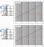
Changing N will have no effect on SPL, only the HF dispersion and extension.
See attached screen grabs for your dimensions with N = 5 and 10. Notice SPL level is unchanged, only HF bandwidth limit changes.
I think that sounds just fine. This is a Configuration 2 symmetric ESL with 6 electrical segments. There would be little point to increase number of segments with your fL fixed at 200Hz. As I’ve mentioned before, Configuration 2 does require a little more attention to resistor values for the first 2 segments and the first one in particular has a larger influence on the response slope in the top 2 octaves than with Configuration 1. However, since you have measurement equipment and plan to use the Behringer EQ/crossover, it should not be a concern.I'm thinking my panel, having 10.5" x 46.5" emitting area, should have 11 segments with 12 rods per segment, 132 rods total. Does that sound about right?
It would be best to put any extra rods in the outer segments.So where would I put the 2 extra rods ? Would it make a lot of difference if I used 14 rods in the center segment and 12 in all other segments? Or would it be better to add 1 extra rod to the edge segments?
Attachments
Reason for seg build
Hi The reason I'm building these panels is to have crystal clear vocals in the lower registers, My Acoustat 2+2 are slightly veiled, it drives me buggy, I planed on stacking these panels 3 high to sit beside the Acoustats , Acoustats being the bass panels, Will this work , or am I wasting my time? I will be bi-ampg using a dbx driverack 260 or 482
Al
Hi,
My 2cts from personal experience.A larger number of segments helps fighting wire-wire capacitance, which causes off axis response somewhat different than predicted. So it could be made a bit broader and more uniform.
In one of my experiments I have used as many as 24 segments for 250mm wide diaphragm. Off axis response was somewhat better with that many segments compared to 7, despite that simulation suggested no difference.
Regards,
Lukas.
Thanks Bolserst - nice pictures!
The attachment below shows the idealised circuit diagram for a segmented ESL with an odd number of identically sized segments. As Bolserst advised, the resistor values for two of the segments are not the same as the others (25% lower).
I expect that if you are using a large number of segments, satisfying Bolserst's formula given above, then the resistors can all be made the same. Additionally, the leading resistor feeding the ESL (the R/2 in the figure) would normally be omitted, so the centre segment is connected directly to the transformer, and instead a smaller resistor, usually of the order of 1 ohm, is inserted into the primary circuit of the transformer. This is required anyway to prevent the transformer from saturating and the amp from sickening when/if it tries to drive dc into the transformer. This resistor can be tweaked to adjust the top end of the frequency response as required.
regards
Rod
Would (11) 12-rod segments satisfy the formula such that I could omit the leading resistor on the center segment as suggested above?
Yes. You can omit the leading resistor and instead use a ~ 1ohm resistor on the primary side of your transformers.Would (11) 12-rod segments satisfy the formula such that I could omit the leading resistor on the center segment as suggested above?
Agreed. I know we have discussed this a few times in some other threads. If cross bars are made from aluminum( ie like Audiostatic) instead of a non-conducting material, you will get even more coupling of HF signal from the inner segments to the outer. I posted a plot showing how the HF roll-off in the outer segments is not as expected when capacitive coupling is not considered.…A larger number of segments helps fighting wire-wire capacitance, which causes off axis response somewhat different than predicted. So it could be made a bit broader and more uniform...
http://www.diyaudio.com/forums/plan...ostatic-baffle-step-filter-4.html#post3385741
Note that this is much more of a problem for full range ESLs where fL is set low and the ladder resistors are of higher value.
For hybrid ESL with fL>200Hz it starts to become a non-issue.
Hmmmm…will need to think on this for a bit. What frequency were you thinking of crossing at between the Acoustats and the potential mid-high segmented panel? If chosen properly, you might be able to dispense with the Acoustat mixer circuit and drive the “woofer” panels directly from the LF transformer and your new mid-high segmented panel from the HF transformer.Hi The reason I'm building these panels is to have crystal clear vocals in the lower registers, My Acoustat 2+2 are slightly veiled, it drives me buggy, I planed on stacking these panels 3 high to sit beside the Acoustats , Acoustats being the bass panels, Will this work , or am I wasting my time? I will be bi-ampg using a dbx driverack 260 or 482
Hi,
If you are aiming at broad dispersion pattern and highest possible sensitivity, 20-30cm wide panels should give no big problems with wire to wire capacitance IMO. It should also serve down to 200hz well enough. Bolserst comment about full range system is correct. With the same wire to wire spacing and higher d/s(or height) the ratio of capacitive reactance and segmentation resistor's resistance becomes much more of an issue.Also the energy contributed by center segments becomes smaller compared to whole panel.In general, thinner panels are easier to design having broad dispersion than wide ones.However, I am still not convinced than very wide dispersion pattern leads to best subjective listening experience. As it causes more reflections from surrounding surfaces. A room can easily change the equation from virtually flat to fluctuations of 10 or even 20db.
Cheers
Lukas
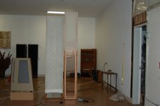
What fabric do you use for the socks? I also wanna replace them at my Acoustats (although I'll use black/dark fabric).Rough idea of what I'm attempting, socks are extras that I made for the acoustats, fit nice, sure are see through compared to the acoustats
The transition from HF to LF transformer occurs over a broad range from 100Hz to 1Khz.Bolserst, I was hoping for around 200hz there abouts, I'm not sure where the hf trany takes over at.
Frequency response of Acoustat interface posted here: http://www.diyaudio.com/forums/plan...cls-ii-stators-best-way-do-2.html#post3822064
I would think crossing at 200Hz is low enough that you could drive the Acoustats directly from the LF transformer and use your dbx EQ/crossover to handle any required shelving below the 200Hz crossover frequency.
Can you clarify what you mean be vocals in the lower registers? Do you mean lower frequencies? Or lower SPL levels. If lower frequencies, could you estimate the frequency range of concern? The reason I ask, is that some owners have noted an improvement in clarity in the 200Hz – 500Hz range when upgrading the 0.01uF capacitors used in the mixer circuit.Hi The reason I'm building these panels is to have crystal clear vocals in the lower registers, My Acoustat 2+2 are slightly veiled, it drives me buggy
The other question I had, was you mention clarity as a reason you are considering the addition of a segmented panel, but not improved HF dispersion. Are you happy with the size of the sweet spot with your 2+2s?
Last edited:
OK, I have a couple of questions before I order parts (indulge me please... I'm a dummy with all things electronic):
The spreadsheet gives a resistor value of 80.66 Kohms for my 11-segment panels.
For symmetric configuration 2, and with a 1 Ohm resistor in the primary, I can omit the lead resistors and use R resistors in lieu of 0.75R resistors for the first adjacent left/right segment pair, then R resistors for the remaining (4) outer segment pairs.
Is that correct?
OK, now what resistor type and wattage ratings should I use?
thanks,
Charlie
If you have a lot of HF content, the resistor toward the center see fairly high voltages. 1000V is a reasonably expected voltage level (after an 80:1 step up). With your 80KOhm resistor value, this is 12mA or 12W. Unless you are doing sustained high power tone testing at these frequencies, these are not average levels. Then again, you may see more than 1000V as well.
I am using Vishay 2W resistors in series to spread the load. In my case, the segments toward the center have 5 or 6 of these resistors in series (to add up to the required value), and toward the end have 2 in series.
I am getting them from Mouser. Here is a link to a 10K, the others can be found from here. They are pretty inexpensive at a dime each.
PR02000201002JR500 Vishay / BC Components | Mouser
- Status
- This old topic is closed. If you want to reopen this topic, contact a moderator using the "Report Post" button.
- Home
- Loudspeakers
- Planars & Exotics
- Thinking about a segmented wire stator ESL