Thanks Bolserst - nice pictures!
The attachment below shows the idealised circuit diagram for a segmented ESL with an odd number of identically sized segments. As Bolserst advised, the resistor values for two of the segments are not the same as the others (25% lower).
I expect that if you are using a large number of segments, satisfying Bolserst's formula given above, then the resistors can all be made the same. Additionally, the leading resistor feeding the ESL (the R/2 in the figure) would normally be omitted, so the centre segment is connected directly to the transformer, and instead a smaller resistor, usually of the order of 1 ohm, is inserted into the primary circuit of the transformer. This is required anyway to prevent the transformer from saturating and the amp from sickening when/if it tries to drive dc into the transformer. This resistor can be tweaked to adjust the top end of the frequency response as required.
regards
Rod
Attachments
...It also means my next panels (which I am shooting for much closer to full range) will need 22-25 segments. This will save many hours of trial and error!
OK! I can't let that teaser go without asking if you could give us a preview of your next panel? Any change in your 1/2" egg crate (you use the thick acrylic ones from your source, right?), 0.035 TIG, and E6000 adhesive? Going to a larger panel size? Crossover freq? Got some photos??!!
I'm interested to see you have any problems getting the rolled wire straightened. With a roll of continuous wire, you may be able to stack two louvers face-to-face with a threaded rod at each end to set spacing, and them wrap them--- doing both stators at once would save a lot of time!
Thanks Charlie, that's an excellent idea about the double wrap, that solves the wire issue I was having in my mind, I was thinking that the roll wire might go all springy-sprongy on me. I don't think keeping the wire straight will be an issue with your technique, I have a MIG welder and have played with the wire a bit. It doesn't really have that strong a memory like spring wire does.
And I wonder if it would be possible to come up with some sort of electronic switching where a user can switch between unsegmented and segmented operation. I don't know how complicated that would be with so many segments though. Unfortunately, while I'm a pretty good "wheel builder", I'm not much of a visionary "wheel inventor", so someone with a higher rank than me would have to work out something like that.
Take good care all, Neil

Just skimming over this thread with not much attention paid, other than the main objectives and parameters you are working with, Charlie.
Wishing the best of luck to you in this endeavor, lots of pics requested once you get where you are going.. please..
cheers
-wreck
Thanks Wreck,
I've got the welding rods and I'm waiting on the plastic grids to arrive before I draw up the panel. The new panel will replace the panel in my existing bi-amped, beam splitter hybrid ESL and will use the same 75:1 trannys, 2.7Kv bias supply and 220Hz woofer to panel crossover.
I'm still thinking of rigging up some mechanism to make the panel switchable from non-segmented/narrow dispersion to segmented/wider dispersion. Of course, this would require unique EQ curves for each dispersion mode but I could do that part with the memory settings on my digital EQ. Rigging a switching mechanism on the high voltage side is another matter.
Last edited:
Thanks Bolserst - nice pictures!
The attachment below shows the idealised circuit diagram for a segmented ESL with an odd number of identically sized segments. As Bolserst advised, the resistor values for two of the segments are not the same as the others (25% lower).
I expect that if you are using a large number of segments, satisfying Bolserst's formula given above, then the resistors can all be made the same. Additionally, the leading resistor feeding the ESL (the R/2 in the figure) would normally be omitted, so the centre segment is connected directly to the transformer, and instead a smaller resistor, usually of the order of 1 ohm, is inserted into the primary circuit of the transformer. This is required anyway to prevent the transformer from saturating and the amp from sickening when/if it tries to drive dc into the transformer. This resistor can be tweaked to adjust the top end of the frequency response as required.
regards
Rod
Great stuff Rod, I sure appreciate your help. Before I solder wires together I will post my interpretation of the resistor values and layout for a sanity check here.
Charlie
Didn't mean to be a tease, Neil...
I just got the 1/2" louver panels in yesterday, so I'm just getting started. Yes, still the same TIG rod and adhesive. These will be about 22x48 with a d/s of 0.125. I have some 1/8" thick acrylic strips that should make good spacers. Rest assured I'll take many photos along the way and document everything on the website.
My main issue with the current setup I have is the 200Hz crossover - right in the middle of some great cello music. With the larger d/s and some mechanical damping of the resonance I'm hoping to extend the low end to 40 or 50Hz.
Didn't mean to be a tease, Neil...
I just got the 1/2" louver panels in yesterday, so I'm just getting started. Yes, still the same TIG rod and adhesive. These will be about 22x48 with a d/s of 0.125. I have some 1/8" thick acrylic strips that should make good spacers. Rest assured I'll take many photos along the way and document everything on the website.
My main issue with the current setup I have is the 200Hz crossover - right in the middle of some great cello music. With the larger d/s and some mechanical damping of the resonance I'm hoping to extend the low end to 40 or 50Hz.
That's quite interesting. What will radiating area be? While approaching and exceeding something like 0.4m2 it makes increasingly more sense to run(or at least try) speakers full range. If one would manage to set resonance at about 40Hz it would make an impression of quite realistic bass, given that few instruments and recordings produce significant output below that.
I have spent coutless hours trying to match a single dipole sub with semi-full range ELSs(50Hz and up) and still without sub the sound was a lot more pleasant and relaxing, even though a DSP was used. Maybe others have had a different experience..?
Cheers
Lukas
Last edited:
Radiating area will be about .61m2 after subtracting the spacer area.
Hi,
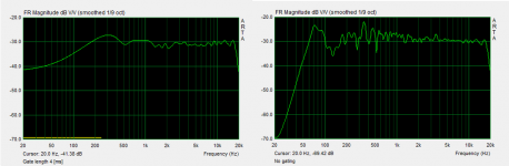
IMO your design should be capabel of reproducing full range given that suitable trafos are used. In the attachment below are gated and non-gated measurement of a smaller speaker(0.3x1.5m) running full range. The ragged frequency response in the right diagram is due to room artifacts which are not affecting gated measurement. The left diagram is gated to 4ms, so bass response is cut off and not measured.
If we try to extrapolate, it's quite possible that your speaker will show ~3-5 db drop at perhaps 70-90Hz, before reaching resonance.If design goal is to achieve +/-2 db in operating range, it's possible only little equalization could be required(1-3db).
I am a little bit skeptical about designs which don't incorporate dust protection of any kind. Dust particles will exhibit buzzing noises at low frequency. This is definitely an evil for sound. The buzz has high frequency content and is unlikely to show up in THD/IMD measurement; also it's not easy to recognize in a spectrum analyzer because the range is broad and low in level. Still very easy to hear while listening to sine waves

Even a fine fabric is a good improvement as well as it reduces Q of fundamental resonance a lot. Too thick a fabric and mid/high frequencies suffer... A domain for experimentation.
Hope this helps a little.
Cheers
Attachments
Last edited:
Hi Charlie
I second the suggestion of full-range ESL. When I built mine I fully expected the beautiful midrange and tops - wonderful clarity, especially vocals and acoustic instruments, but I had not expected the fantastic bass - seamless, fast, and without any horrible cabinet resonances. Now I clearly hear differences between different types of drum, which were not as audible with conventional speakers. Cello should be great!
Yes you will need to put some thought into the transformers - operation at 50 Hz requires a lot of turns = high leakage inductance and high winding capacitance - if you don't get the balance right you will loose the top end of the frequency response.
Also, panel height might be an issue. Check out discussion in Baxandall, and my paper, about frequency response versus panel height. Below a certain frequency, the ESL response will change from line source (what you want) to point source (not wanted for the segmented design). The frequency response will fall of in proportion to f rather than sqrt(f), so you loose a little bit of bass at useful listening distances. The response changes at f = c.r/h^2 where
c = speed of sound 330 m/s
r is listener distance 3 m?
h is height of ESL panel 48" =1.3 m. Actually this should be doubled to account for reflection from the floor. use h = 2.6 m
hence the change occurs about 150 Hz. Its getting down into the region where room effects are important too, so probably not critical.
Probably a carefully tuned (I.e. damping) diaphragm resonance will fix the problem. The best damping cloths are monofilament mesh fabrics such as used for particle filters and screen printing - cheapest I've found is at Ali-express. Look up the Saarti acoustic filter fabrics for guide on choice of fabric http://www.saatiamericas.com/SaatiTech/pdfs/Brochures/SaatiFil%20Acoustex.pdf you probably need something near 40 rayle.
If you tune the diaphragm resonance at 50 Hz, say, then the cutoff frequency for the RC transmission line should be about 2.5 times higher - 120Hz ish.
regards
Rod
Thanks Rod,
But I'm not ready to take plunge into full range just yet. For this project, to be done on the cheap, I'm just replacing the 1'x4' perf panels in my current hybrid speakers with segmented wire panels. Although positive results may indeed push me over the edge-- it's a damn psychosis after all.
But I'm not ready to take plunge into full range just yet. For this project, to be done on the cheap, I'm just replacing the 1'x4' perf panels in my current hybrid speakers with segmented wire panels. Although positive results may indeed push me over the edge-- it's a damn psychosis after all.
Thanks for the link Rod,
I have acquired a selection of silk screen fabrics that I was planning on using to tune the damping. The ones from Saati look to be the better choice, but I'll start with what I have on hand.
My apologies to Charlie, I did not mean to hijack his thread with discussion of my build.
I have acquired a selection of silk screen fabrics that I was planning on using to tune the damping. The ones from Saati look to be the better choice, but I'll start with what I have on hand.
My apologies to Charlie, I did not mean to hijack his thread with discussion of my build.
Thanks for the link Rod,
I have acquired a selection of silk screen fabrics that I was planning on using to tune the damping. The ones from Saati look to be the better choice, but I'll start with what I have on hand.
My apologies to Charlie, I did not mean to hijack his thread with discussion of my build.
Hey feel free, it's all good stuff!
Hi,
a fullrange ESL certainly concentrates on just the ESL part, while a hybrid also asks for some thinking and great effort with dynamic speakers.
But apart from this and maybe optical reasons it remains a fact that choosing FR means to loose on basically every single important parameter.
Its perfectly understandable if someone doesn't want to spend the required effort and costs for a decent bass solution, or one dislikes the optics of additional cabinets.
That's fine, but gimme a break with that talk of superior sonics of a FR.
While building a decent hybrid panel is not overly difficult, a decent FR requires more knowhow and experience than the typical 1st-time builder has.
The risk to end up with a panel that performs poorly with regard to efficiency, linearity, dynamic range, stability and safety, and not least sonic deficiencies, is high.
jauu
Calvin
Al may be asking two questions here:
Does it behave as a reed - vibrating the rod as air passes such as the reed of a woodwind. Since the rod is supported every 1/2", and the rod is very stiff (as compared to a reed) if there were vibration induced, it would be very high in frequency given by the formula:
fo = 1/2pi * sqrt (k/m - R^2/2m^2)
With some assumptions about the mass and stiffness of the rod, we can place the vibratrion's frequency well in the the 100s of kHz.
The second question Al may be asking is if the space creates an effect similar to a whistle - air rushing over a split causing an oscillation in the air pressure.
This is not possible. The whistle effect is caused by a vortex being set up at the point of the split, then the collapse of that vortex in the body of the whistle. This process is repeated quickly causing the oscillation sound of the whistle. This process relies on a chamber and a single split of air movement. Since the rods are closely spaced, there are many splits of air passing through simultaneously. The split directly next to the narrow one caused by the proximity to the louver vane is much wider, effectively opening the chamber required for the whistle effect, and breaking any vortex.
I've not built any panels with light diffusers before. I'm wondering if a .375 plastic grid with tiny .035 rods will have enough mass to resist audible ringing. I've not heard anyone say that's an issue so I'm hoping it won't be. I'm expecting to have the diffusers early next week.
My experience is that this is not a problem. If I tap on the 3/8" panels the predominant frequency is the resonance of the diaphragm. There is also a lower component which is the resonance of the panel itself, but that is lower than the diaphragm resonance yet. In the case of the 15x36 3/8" panels I built, the diaphragm component was at 83Hz, the panel resonance was at 31Hz (with the extra stiffening rods on the back).
The panels I made with 1/2" louvers were considerably stiffer and I was not able to even measure a panel resonance.
The panels I made with 1/2" louvers were considerably stiffer and I was not able to even measure a panel resonance.
- Status
- This old topic is closed. If you want to reopen this topic, contact a moderator using the "Report Post" button.
- Home
- Loudspeakers
- Planars & Exotics
- Thinking about a segmented wire stator ESL