Re audibility: One thing you have to keep in mind, a cut-off frequency might well be above the threshold of audibility - 20 kHz say, but there will be phase changes occurring in all content approximately 1 decade below that - down to 2 kHz say. I would be very surprised if the phase changes were entirely inaudible.
Regards
Rod
Regards
Rod
aaaAaah…ok. You incorrectly used 11 segments in the spreadsheet since you plan to have 11 physical segments. Remember for a symmetrically segmented ESL, the number of electrical segments = (number of physical segments + 1)/2. I attempted to clarify this back in post#79
http://www.diyaudio.com/forums/plan...-segmented-wire-stator-esl-8.html#post4192217
For your 11 physical segments you should be modeling with 6 electrical segments in the spreadsheet. The top figure in the Attachment #1 shows what the spreadsheet is using to model the on-axis response shown in the plot. Each of the segments has the same size/capacitance = C shown in the spreadsheet. Each of the resistors has the same value = R shown in the spreadsheet except the first, R1 is half of R.
Now, if you want to place these 6 electrical segments into a symmetrical configuration to improve polar response you start by placing the first segment in the middle. Then you take the second segment, split it in half, and place each half on either side of the middle segment. Next take the third segment, split it in half, and place each half to the outside of the second segments halves. Etc…
To further improve dispersion, you can cut the size of the center segment in half so it is the same size as the outer physical segment portions. Since you have reduced the area of the center segment, the HF response would droop if no other changes were made. To keep flat on axis response, you can adjust the value of the resistors feeding the center segment down. This is Configuration 2.
In your case, with N=6 & fL=200Hz, R= 147Kohm; with fL=220Hz, R= 133.7Kohm.
With 40Vrms input and 1:75 step-up ratio, the worst case RMS voltage and power dissipation requirements for the resistors are shown in Attachment #2. Remember you don’t need to consider R1 since you are moving that to the primary side. Obviously music does not contain continuous HF tones, so these values are rather conservative. If it was me, I would probably use two 68K/2W resistors in series between each segment. If you plan to do a lot of high SPL testing, you might consider three 47K/2W resistors in series.
OK... needing a sanity check before I order resistors for the Version 2 configuration, 6 electrical segments, 11 physical segments, 147 Kohms/segment:
Using a 1 Ohm resistor at the input of the transformers allows omitting the lead resistors; leaving 5 segment pairs with (2) 68K resistors in series between each segment, x (2) stators = (40) 68Kresistors, total.
I'm still not clear on whether ALL resistors can be 68K or if the first L/R segment pair need to be 0.75R (about 56Kohms).
I have in my cart at Mouser right now the following metal oxide film resistors:
(8) 3 watt, 68K (first pair same as remaining pairs)
(8) 3 watt, 56K (optional in case first pair need to be .75R)
(32) 2 watt, 68K for remaining segments
does that sound about right?
Last edited:
You are using enough segments that either option will work fine. The only difference is that when you use R instead of 0.75R for the first L/R segment pair you will need to use a slightly lower value for the resistor in series with the primary. With either option you will probably need to adjust the primary resistor based on measurements/listening to get the top octave how you want it anyways. If you are planning to purchase higher power resistors for the first L/R segments anyways, I would use the 0.75R so that the adjustment range on the primary resistor is slightly less critical. Just a personal preference...I'm still not clear on whether ALL resistors can be 68K or if the first L/R segment pair need to be 0.75R (about 56Kohms).
Values, power ratings, and number of resistors look good(8) 3 watt, 68K (first pair same as remaining pairs)
(8) 3 watt, 56K (optional in case first pair need to be .75R)
(32) 2 watt, 68K for remaining segments
does that sound about right?

Re audibility: One thing you have to keep in mind, a cut-off frequency might well be above the threshold of audibility - 20 kHz say, but there will be phase changes occurring in all content approximately 1 decade below that - down to 2 kHz say. I would be very surprised if the phase changes were entirely inaudible.
Regards
Rod
Hi,
I am a bit sceptical about audibility of phase shifts, unless they are very sharp, which is quite unlikely at one decade below filtering.
The argument is, that the speaker is typically listened from varying distances. This alone will cause phase shifting, heavily increasing with frequency.
It's quite fascinating our sound-resolving apparatus can compensate for such things, and it's quite probable that there are biological adaptations involved.
Even more, a +/- 1.5 db speaker could sound good in a typical household room where it becomes closer to +/- 15 db(in extreme cases).
Also statistical measurements must be made extremely cautious to exclude other side-effects.
Regards,
Lukas
Hi Bazukaz
Understood. I'm not directly familiar with the literature on this, but I understand our ears/brain determine direction of sound by a combination of phase differences and amplitude differences. At highish frequencies, once the wavelength is smaller than the distance between our ears (and phase difference becomes an ambiguous measure), the mechanism switches to amplitude only, so apparently we are not very sensitive to phase differences above a couple of kHz. So you have good reason to be sceptical.
However, if you compare the high frequency performance of a good ESL and a good conventional midrange/tweeter (there are some stunning full rangers around) the ESL has the clear edge on clarity, especially for instruments like triangles, symbols - there is no mistaking the improved 'metallic' sound with the ESL. Given that both speakers have a good flat frequency response in this range, perhaps the difference can be explained in terms of phase coherence.
My thought for the morning..
best wishes
Rod
Hi,
Some well-made three way dynamic systems can sound surprisingly good. When I was 19y old I have made one, during a period of about 1 year, and it's very clean across the spectrum, and very neutral sounding.
IMO one of the main benefits of an ESL is it's a) more directive sound distribution pattern & b) dipole nature.
The first makes us hear more sound from the speaker compared to reflections.
The second can reduce the effect of standing waves in the room, depending on placement, which mostly affects lower frequencies. That's the reason why an ESL can produce nice bass, despite it's diaphragm resonances, which, in most cases, have higher Q and longer decay compared to sealed or ported woofers.
I have done measurements about those points in near and far field conditions and it confirmed the hypothesis.
Edit:
Large radiating surface has another effect on low frequencies : many room resonances are excited, and this may have an averaging effect to them. I recall some sources claiming that multiple woofers sound better because of this effect. A simple example is one vs two sub-woofers : doubling them causes much less subjective differences in bass reproduction while walking over the room. Of course placement is an important factor as well.
Regards,
Lukas.
Last edited:
These qualities can be achieved in other type of plane or line source dipole speakers as well. I'm especially interested in AMT speakers as they can achieve high SPL, sensitivity and low distortion with a narrow dipole driver (for example 97 dB sensitivity and 190W power handling in the Mundorf AMT27D). ESL panels are typically are wider and have lower SPL but typically can go lower because of panel size. Does anyone have a reference to a comparison in dispersion pattern between a wide and narrow dipole? Or the difference in dispersion between a segmented ESL and a narrow dipole?IMO one of the main benefits of an ESL is it's a) more directive sound distribution pattern & b) dipole nature.
The first makes us hear more sound from the speaker compared to reflections.
The second can reduce the effect of standing waves in the room, depending on placement, which mostly affects lower frequencies.
For bass I think dynamic drivers in a dipole configuration is the best option if you need high SPL and reasonable size.
These qualities can be achieved in other type of plane or line source dipole speakers as well. I'm especially interested in AMT speakers as they can achieve high SPL, sensitivity and low distortion with a narrow dipole driver (for example 97 dB sensitivity and 190W power handling in the Mundorf AMT27D). ESL panels are typically are wider and have lower SPL but typically can go lower because of panel size. Does anyone have a reference to a comparison in dispersion pattern between a wide and narrow dipole? Or the difference in dispersion between a segmented ESL and a narrow dipole?
For bass I think dynamic drivers in a dipole configuration is the best option if you need high SPL and reasonable size.
Hi,
In the current realm of Hi-Fi active speakers, sensitivity in the high frequency range is not that much important as it may seem, unless the systems are used for bars or concert halls. The average power requirements fall above few hundred hertz quite fast. Peak power requirements fall as well, although not that fast.
I am sure(would be glad if someone pointed to a test showing otherwise) that Mundorf AMT27D would destruct almost immediately if exposed to 190W continous power.
So, the total output of the system is in most of cases restricted by low and low-mid-range reproducers.
To obtain a matching 97db sensitivity and power ratings would require large drivers in the order of 18" and, perhaps, not in dipole configuration.
And, of course, not every one prefers high output levels. My ELS are in the order of 82-84 db efficient, and it's perfectly suitable for casual listening. Others may have different habits of course.
Now about the dispersion pattern of driver you have pointed out. According to it's measurements :
http://www.lautsprechershop.de/pdf/mundorf/mundorf_amt27d11.pdf
it shows ~15db drop at 20 kHz & 15 degrees off axis in vertical direction. That's not good. Segmented line-source wire ESL could easily achieve far better than this. However waterfall spectrum is not too bad. It's difficult to predict subjective sound qualities based purely on it's specifications.
Regards,
Lukas.
Last edited:
As I see it, it is more like 7 db and you mention the vertical direction.
I doubt a vertical segmented ESL does improve anything at all in the vertical direction.
The horizontal direction seems far more important to me and at 20 kHz it drops about 1 db! Can you show me such, or better figures of and ESL 20kHz and how much it drops in horizontal direction?
Edmund
I doubt a vertical segmented ESL does improve anything at all in the vertical direction.
The horizontal direction seems far more important to me and at 20 kHz it drops about 1 db! Can you show me such, or better figures of and ESL 20kHz and how much it drops in horizontal direction?
Edmund
.JPG)
Hi Charlie,
Nice! What kind of wire are you using?
I notice you are using a different approach to stretch your Mylar. Can you show us what you have done and how you like it?
Wachara C.
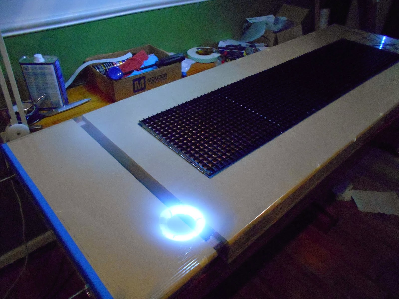
I'm not sure I will like it. Since the wires are vertical and electrically segmented, I figured I needed to go with horizontal spacers and tension the diaphragm only in the vertical direction. So I built a mechanical jig 69" x 24" to stretch the diaphragm. I figured better to make the jig big than too small, since I didn't know if the film would elongate linearly and if it didn't, the added size would provide a section in the center that was more or less uniform.
However, after my first attempt using 1.5% elongation I noticed the diaphragm was rather loose around the edges, as I applied only enough horizontal tension to pull the wrinkles out, and I was afraid it would rattle and/or the diaphram would be pulled into a stator.
Not to mention I became uneasy because I had pushed the limit of the 100 x d/s rule (.06 d/s and max spans were 5.7").
So, I ripped off the first diaphragm, and then increased the vertical tension to 1.8% and added a fair amount of horizontal tension by hand with tape tie-downs along the edges of the jig.
The diaphragms are now nice an tight and I'm no longer worried about them being pulled into the stators; although I'm sure the resonance frequency is now much higher that it would have been at 1.5% elongation.
I will assemble the panels fist thing in the morning but I'm spending the rest of the weekend with my GF (a.k.a. China Doll) and I haven't ordered the resistors to build the filter network yet anyway. It may be next weekend before I hear the panels.
Last edited:
Do you insulate your stator wires? From the picture, they sure look like uninsulated.
Yes, there's about 6 mils of clear paint on the wires.
")
Hi Charlie,
Very nice looking work. By the way, I am a little bit concerned about long-term stability of membrane after stretching to close to 2% of elongation. Different brands of polyester film are not made in the same way, so it may hold it for long, or may not. If doesn't, there may be a possibility to add some silicone dots. However there are some critical tricks with application of those, while quite simple, but required to avoid buzzing noises at higher diaphragm excursions.
Just curious, maybe you have already mentioned previously, what is the thickness of the film?
I hope your project goes well.
Regards,
Lukas.
When I bought the film on Ebay it was advertized as a 10 meter roll of 6- micron Dupont Mylar C but I didn't see any brand logos on it.
The slackness I saw after the first attempt at 1.5% was only near the vertical side edges because I had not applied any horizontal tension. Had I used closer spacing between the supports I would have been comfortable with 1.5% vertical with a bit more horizontal stretch. I guess time will tell.
BTW, I finished assembling the panels:
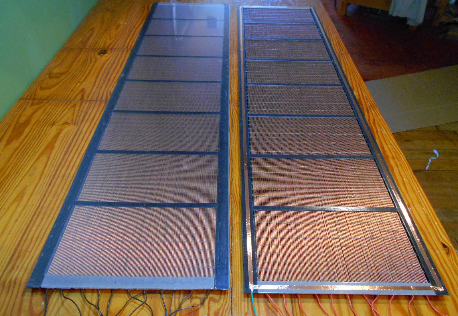
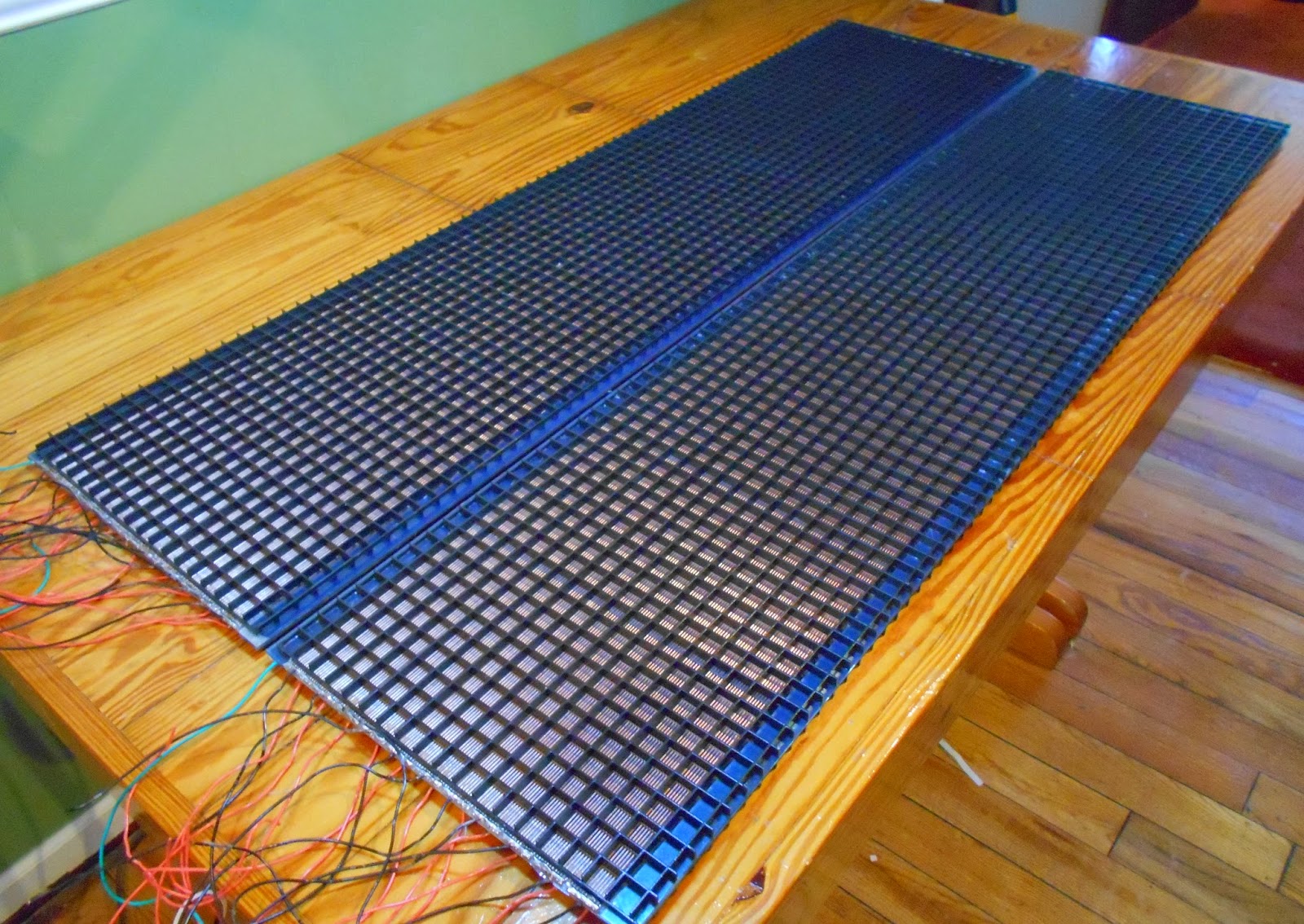
Last edited:
Hi,
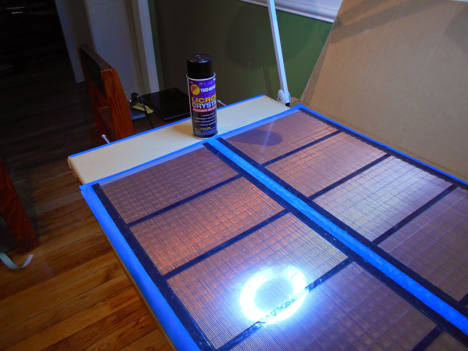
I see that you have applied copper strips on the other stators compared to which contain the film. It may work , but the copper will eventually be coated with oxides; also the contact is not the best overall. Depending on resistance and properties of the coating it may lead to problems in long-term, after corona slowly disintegrates the coating below copper, and charging of the film could become compromised.
There is another method which reduces possible problems to a high degree:
a) first apply the coating to the membrane
b) glue copper strips on stator which holds membrane, on top of the coating
c) apply an additional coat on the edge between copper and coating, preferably with lower S/R resistance, with a small brush.
Edit :
If you prefer using older formulations of licron crystal(manufactured before 2014 or so), keep in mind that it tends to be severely degraded by UV light. I do not know if they have provided any means to distinguish between different formulations. That means a speaker without relatively thick cloth should not be placed near a window. A coat in the order of 10^7 ohms*sq will last longer, but the optimal value of 10^9 is not going to last long when exposed to the sun.
Regards,
Lukas.
Last edited:
- Status
- This old topic is closed. If you want to reopen this topic, contact a moderator using the "Report Post" button.
- Home
- Loudspeakers
- Planars & Exotics
- Thinking about a segmented wire stator ESL