...Actually doesn't matter if it is TMC or other kind of compensation, it's important if some element of the compensation is connected directly to the amp output, like Cherry compensation or the compensation I used in my CFA amp...
For all other type of nested NFB, TPC included, Tian probe placed in GNFB loop should show all data about stability of the amp in simulation...
Ok, now we understand each other
")
It seems I did understand your view correctly, that there are two different cases of nested feedback that are analysed differently.
But I do not think this is correct.
First I should be clear that I take "nested feedback" strictly - where one cut will open all the loops.
This actually becomes tricky once we include second order effects, like reverse transmission thru the feedback network and I am not yet clear in this case.
But for the basic case I am confident that all nested loops should be checked the same way, where the one cut will open the loops, that is, in the inner loop.
The probe in the outer loop will correctly tell if the amp is stable or not, so your tests for this were correct.
But it can underestimate how far the amp is from instability, just as it does for TMC, for instance.
I look forward to your pictures, this discussion will not delay my article for Jan, on the contrary, it helps me see if my ideas are clear.
Best wishes
David
Ok, now we understand each other
It seems I did understand your view correctly, that there are two different cases of nested feedback that are analysed differently.
But I do not think this is correct.
First I should be clear that I take "nested feedback" strictly - where one cut will open all the loops.
This actually becomes tricky once we include second order effects, like reverse transmission thru the feedback network and I am not yet clear in this case.
But for the basic case I am confident that all nested loops should be checked the same way, where the one cut will open the loops, that is, in the inner loop.
The probe in the outer loop will correctly tell if the amp is stable or not, so your tests for this were correct.
But it can underestimate how far the amp is from instability, just as it does for TMC, for instance.
I look forward to your pictures, this discussion will not delay my article for Jan, on the contrary, it helps me see if my ideas are clear.
Best wishes
David
Hi David,
I could be that as I see it is not correct, but my simulation was confirmed in real amps.
If you look again #post 806 http://www.diyaudio.com/forums/solid-state/182554-thermaltrak-tmc-amp-61.html#post4755022 ,first plot is where Tian probe is in correct place, it cover both, GNFB and nested NFB from the output to the VAS input(R23).
Next example is from my CFA, first plot is correct as it cover again GNFB and nested NFB via C8.
Best wishes
Damir
Attachments
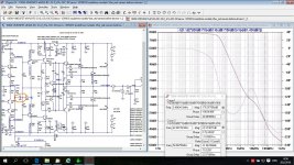
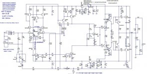
This is my TT VFA but now with different compensation, instead TMC I used here OITPC(Output Inclusive Two Pole Compensation), similar to the one I used in mine CFA.
With some other changes and simplification distortion is lower and the amp is more stable with better Phase and Gain Margins.
Damir
With some other changes and simplification distortion is lower and the amp is more stable with better Phase and Gain Margins.
Damir
Attachments
Last edited:
Does C22 change the feedback from TMC to OITPC?
It is not TMC, but TPC (R5, R6 and R30, and C22 is connected from the output to the mid TPC point. I just call it OITPC, probably not in accord with established abbreviations.
This is my TT VFA but now with different compensation, instead TMC I used here OITPC(Output Inclusive Two Pole Compensation), similar to the one I used in mine CFA...
So the loop plot is with the Tian probe in the outer loop?
I need to think more about the loops around the VAS, but first impression is that it looks pretty nice, my compliments.
Best wishes
David
This is my TT VFA but now with different compensation, instead TMC I used here OITPC(Output Inclusive Two Pole Compensation), similar to the one I used in mine CFA.
With some other changes and simplification distortion is lower and the amp is more stable with better Phase and Gain Margins.
Damir
How close is this to the original? Can it be built on the original boards with minor modifications?
So the loop plot is with the Tian probe in the outer loop?
I need to think more about the loops around the VAS, but first impression is that it looks pretty nice, my compliments.
Best wishes
David
Thanks David.
How close is this to the original? Can it be built on the original boards with minor modifications?
It is very close to the original and could be possible to use the original boards with some modification and some components value change.
Thanks David.
You are welcome Damir.
But where is the Tian probe for the loop gain plot?
Best wishes
David
Last edited:
You are welcome Damir.
But where is the Tian probe for the loop gain plot?
Best wishes
David
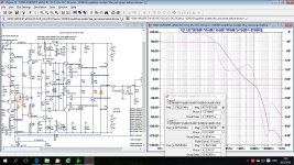
It's like this.
Damir
Attachments
It's like this.
Thank you, I think that is the dominant loop, so we are in accord now.
But I would be curious to study the inner loop, there should be non-minimum phase behavior similar to what we discussed when you noticed it in an earlier circuit.
Could you post here or email me the ASC?
Best wishes
David
Thank you, I think that is the dominant loop, so we are in accord now.
But I would be curious to study the inner loop, there should be non-minimum phase behavior similar to what we discussed when you noticed it in an earlier circuit.
Could you post here or email me the ASC?
Best wishes
David
Hi David,
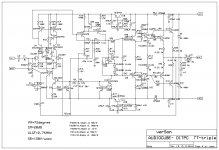
Here is the .asc
BR Damir
Attachments
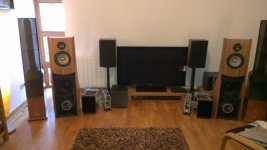
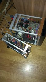
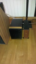
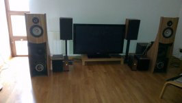
Finally after years I put in boxes mine three channels TMC ThermalTrak amps. When I started with my design it was intention to use those amp to drive majestic Linkwitz Orion loudspeakers. It is here now, not yet completely finished, boxes cover is missing, but it works and sound fantastic. Useded are analog active crossovers designed by Likwitz and the smaller boxes are that.
Damir
Damir
Attachments
Would it not be preferable to have the collector of Q20 connected to the base of Q16 instead of its emitter ?
That is standard way, but in my opinion it has less influence (distortion) connected to the Q16 emitter(actually the Q12 base) and equally protect in case of clipping.
Next step...OITPC as in post 632.
Hi Damir
Discussion in another thread reminded me to have another look at the OITP Compensation and I noticed a bit more this time.
I have found that it works well to put the Bode step in the feedback network, so a capacitor across the feedback resistor R6
I know that Bob Cordell doesn't recommend this because of possible RFI but it looks the optimal way to maximize feedback.
A few European papers refer to this as a "phantom zero" if you want to check the literature.
Have you considered this approach? it may permit you to simplify or reduce the internal nested loops.
Of course, your results are already so nice that the idea is more for educational interest.
Best wishes
David
Hi David,
I know about Cordell recommendation and I agree with him. A capacitor parallel to the feedback resistor helps in some way but introduces problem too. In my compensation the capacitor is connected from the output to the middle point of the TPC compensation, in my case where C5, C6 and R30 meet. In this case I've got much better PM and GM. It's similar to the Cherry compensation, but not exactly, Cherry does not use TPC.
Best regards
Damir
- Status
- This old topic is closed. If you want to reopen this topic, contact a moderator using the "Report Post" button.
- Home
- Amplifiers
- Solid State
- ThermalTrak+TMC amp