I have also been busy with work around house but still audio, mostly work on a <1 Part Per Million Distortion oscillator in the Test and Equipment sub-forum.
That kind of Super Low Distortion is not so easy, I have had to think about new ideas.
If you read the thread then I would welcome your comments.
I think you are correct, the difference should be very small as the circuit now is, but better to have the probe where it should be, then no surprises if you start to modify.
Also people who copy your circuit can learn the correct technique, they may
not be so experienced as you to know when it does or doesn't matter.
Finally, perhaps we are mistaken, sometimes your complicated feedback has not behaved as I initially expected, very educational to understand why.
Best wishes
David
Hi David,
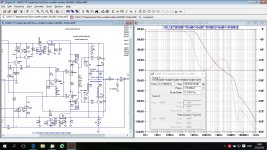
As I expected the Loop Gain plot looks exactly the same as before, not important where Tian probe is.
I want to see only GNFB Loop Gain plot and local FB around VAS is not included here (R23).
BR Damir
Attachments
Should we try to read anything into the phase notch from 30MHz to 50MHz, or do we just ignore it since gain is down around -80dB?
My opinion, just ignore.
... the phase notch from 30MHz to 50MHz, or do we just...
Any problem would manifest as a reduction in PM and GM, there is no hidden trap.
So, as Damir says, not to worry here.
Best wishes
David
It's not that there is a problem at 30 MHz, just that there is some improvement at 50 to 60 MHz that is a bit wasted.
If that zero could be moved down there should be some improvement in PM/GM, but probably not dramatic.
Last edited:
Hi David,
As I expected the Loop Gain plot looks exactly the same as before, not important where Tian probe is.
I want to see only GNFB Loop Gain plot and local FB around VAS is not included here (R23).
Thanks Damir but I still don't think this is correct.
The place you have the probe does not plot a return ratio that corresponds to any real value.
The OPS does see the effect of both R23 and the other loop, so you must place the probe to include them both.
This is similar to the debate about TMC, it took a while to convince everyone that the apparent "outer loop" has no physical significance.
People were mislead by the similarity to Miller compensation, where there is a true outer loop.
Not that I expect it will make much difference in your particular circuit, as I have already noted.
I just want to have it theoretically correct so we have a basis for further work.
Best wishes
David
Hi David,Thanks Damir but I still don't think this is correct.
The place you have the probe does not plot a return ratio that corresponds to any real value.
The OPS does see the effect of both R23 and the other loop, so you must place the probe to include them both.
This is similar to the debate about TMC, it took a while to convince everyone that the apparent "outer loop" has no physical significance.
People were mislead by the similarity to Miller compensation, where there is a true outer loop.
Not that I expect it will make much difference in your particular circuit, as I have already noted.
I just want to have it theoretically correct so we have a basis for further work.
Best wishes
David
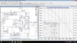
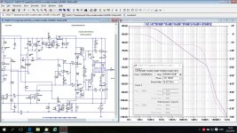
It all depends what you want to see. I wanted to see just global NFB without local NFB around VAS and OPS.
If I include local VAS NFB the plot is here.
Next plot is where both local VAS and TMC NFB are out of global NFB plot.
BR Damir
Attachments
It all depends what you want to see. I wanted to see just global NFB without local NFB around VAS and OPS...
Of course, if you want to see any sub-path then have a look.
But what you plotted in the first example (post#597) does not provide any proof about the stability of the amplifier.
It's not really the "Global NFB", it just looks a bit like it.
The Global NFB is the sum of all feedback at the output.
When there are parallel paths then the feedback can split between them in any proportion, so just to look at one path provides essentially no information.
In your particular amp the path with R23 is very hi impedance so it makes little difference in practice.
But I do think it is important to understand the principle.
Even smart people were confused by this point in the TMC vs TPC debate, so I think we should be careful to show the correct way, even in examples where the practical difference is tiny.
So first example in post #606 is fine.
Best wishes
David
Last edited:
Of course, if you want to see any sub-path then have a look.
But what you plotted in the first example (post#597) does not provide any proof about the stability of the amplifier.
It's not really the "Global NFB", it just looks a bit like it.
The Global NFB is the sum of all feedback at the output.
When there are parallel paths then the feedback can split between them in any proportion, so just to look at one path provides essentially no information.
In your particular amp the path with R23 is very hi impedance so it makes little difference in practice.
But I do think it is important to understand the principle.
Even smart people were confused by this point in the TMC vs TPC debate, so I think we should be careful to show the correct way, even in examples where the practical difference is tiny.
So first example in post #606 is fine.
Best wishes
David
Hi David,
I have to disagree with you in some points.
You are correct in the TMC point as the TMC resistor should be connected before Tian probe, otherwise LG plot will show Miller like plot with to optimistic PM and GM.
I disagree how you interpret global NFB. The NFB around VAS - OPS is not global NFB. Resistor R23 will drop available global LG at low frequencies from 120 dB to 75 dB and keep it at this level up to 10 kHz(in this example) but will not change PM and GM. The plot (post#597) provides all proof about stability.
Best wishes
Damir
... how you interpret global NFB. The NFB around VAS - OPS is not global NFB...
Ok, perhaps the problem is partly the words we use.
I now understand what you call "Global NFB" but this is not a useful path so perhaps that name is not helpful.
The particular path tested in #597 does not show the stability of the amp.
In the worse case a multi-loop amp may require each loop to be tested individually, there may be no one test or measure of stability.
Then the whole idea of "Global NFB" may not even make sense.
But it is possible to simplify the tests of multiple loops if they satisfy certain conditions.
If multiple loops can be cut at one point then that point can be tested like a simple loop, the multiple loops are effectively in parallel.
This is true for the test point of #606 (first picture) but not of #597.
Bode worked this out way back before 1943 but even after I read his book it took me a while to really understand and be sure of this.
I have a more recent link I can search for, if you are interested.
Best wishes
David
Hi David,
I think that GNFB (Global Negative FeedBack) is standard acronym used to describe NFB connected from the output to the - input of an amp.
In my experience, GNFB Loop Gain plot will give me all information I need about stability of an amp. All local FB or compensations will show it's ugly head, if not properly done, in that plot. If that is the case than the simulation of local loops or compensation is useful tool.
I think we had that discussion before, but of course I could be wrong in my assuption?
I am always interested to learn, please search for it.
Thanks and best wishes
Damir
...I am always interested to learn, please search for it.
Here's the reference
http://www.ece.ucdavis.edu/~hurst/papers/FullyDiffRR,CAS.pdf
The main point of the article is not directly about where to cut the loop.
So you don't have to study carefully the whole article and wonder why it is relevant, if you only want the proof.
I said I would do an article on this for Jan Didden's Linear Audio but I have been slow.
At first it was because I wanted to be sure I understood it properly myself.
But now it is because I want to be sure I can explain it clearly.
So I will think a bit more before I write a more detailed reply.
Or perhaps you will read Dr Hurst and find his explanation fits better with the way you think of it.
Best wishes
David
Need to clarify a point.
The correct place for the Tian probe in TMC is directly at the output before any feedback paths split.
If you compare a correct TMC amp simulation you should find this is exactly equivalent to where the probe was placed in #606.
Usually yes, for Miller compensation and similar.
But it is easy to be mislead and think it always applies, as people were mislead in the TMC/TPC debate.
I think you asked about this a while back, when I was still uncertain, so I didn't reply at first.
Then it was discussed in Ric Lee's Output Inclusive Compensation AKA Cherry compensation thread.
That discussion helped me understand better and I think I convinced Ric that he needed to look at more than just the "Global" NFB.
It is possible I convinced him incorrectly but I don't think so.
I have to admit that the answer still does not seem obvious, probably an indication that I have more to learn.
Best wishes
David
..You are correct in the TMC point as the TMC resistor should be connected before Tian probe...
The correct place for the Tian probe in TMC is directly at the output before any feedback paths split.
If you compare a correct TMC amp simulation you should find this is exactly equivalent to where the probe was placed in #606.
In my experience, GNFB Loop Gain plot will give me all information I need about stability of an amp...
Usually yes, for Miller compensation and similar.
But it is easy to be mislead and think it always applies, as people were mislead in the TMC/TPC debate.
I think we had that discussion before...
I think you asked about this a while back, when I was still uncertain, so I didn't reply at first.
Then it was discussed in Ric Lee's Output Inclusive Compensation AKA Cherry compensation thread.
That discussion helped me understand better and I think I convinced Ric that he needed to look at more than just the "Global" NFB.
It is possible I convinced him incorrectly
but I don't think so.I have to admit that the answer still does not seem obvious, probably an indication that I have more to learn.
Best wishes
David
I think you can get pretty far without OLG analysis just by understanding the phase and gain at each stage and looking at the CLG plots. I haven't done OLG analysis on either of my latest prototypes (using "many pole compensation"), and they both work very well. OLG analysis may give you go-no-go info but it doesn't keep you from having to scrutinize individual stages to make your amp work at all loads and to overload well.
I think you can get pretty far without OLG analysis just by understanding the phase and gain at each stage and looking at the CLG plots. I haven't done OLG analysis on either of my latest prototypes (using "many pole compensation"), and they both work very well. OLG analysis may give you go-no-go info but it doesn't keep you from having to scrutinize individual stages to make your amp work at all loads and to overload well.
I look a Loop Gain (return ratio) plot rather than OLG, and, of course, CLG. That was enough for me in all my amps to make a prototypes to work as predicted.
By the way, I can't say that I am very experienced in amp design.
...You are correct in the TMC point as the TMC resistor should be connected before Tian probe, otherwise LG plot will show Miller like plot with to optimistic PM and GM...
Hi Damir
I have done a bit more work on this and now understand it better.
I worked out that both the inner and outer position of the Tian probe will accurately predict if the amp is unstable, so we were both correct on that point
At least, that's the case with the classical, simple model with no feed-forward.
I haven't worked out feed-forward yet, often it is trivial but I suspect it can matter in this sort of case.
Can you explain why you concede that the correct probe point for TMC is before the feedback splits, but don't think it applies here?
The two cases look essentially similar to me but perhaps I have missed some point.
Best wishes
David
Hi Davide, welcome back
I don't remember where I said that (in bold), could you point the post?
Best wishes
Damir
..I don't remember where I said that (in bold), could you point the post?
Hi Damir
It was #608, not so far back.
If you click on the little blue arrow/box at the start of the quote (just after the name) then it will take you to the post where the quote is from.
Best wishes
David
Hi Damir
It was #608, not so far back.
If you click on the little blue arrow/box at the start of the quote (just after the name) then it will take you to the post where the quote is from.
Best wishes
David
Hi David,
I still don't get it, here is post #608:
"
Hi David,
I have to disagree with you in some points.
You are correct in the TMC point as the TMC resistor should be connected before Tian probe, otherwise LG plot will show Miller like plot with to optimistic PM and GM.
I disagree how you interpret global NFB. The NFB around VAS - OPS is not global NFB. Resistor R23 will drop available global LG at low frequencies from 120 dB to 75 dB and keep it at this level up to 10 kHz(in this example) but will not change PM and GM. The plot (post#597) provides all proof about stability.
"
I think I agreed with you how to simulate TMC Loop Gain plot and how to connect Tian probe.
Best wishes
Damir
It may be that I misunderstood what you meant, I will try to explain.
The TMC discussion was before my time but I think there was eventually a consensus that the outer loop Return Ratio was deceptive.
In other words, that we needed to place the Tian probe immediately after the OPS, before the feedback split into two paths (one for the TMC, one for the outer loop).
I think this is correct, essentially we check the inner loop.
I think the situation is similar for any nested loop, that we need to check the inner loop.
I have done some theory that confirms this, in fact I repeated the calculations when I couldn't easily find my notes. This was helpful because I did it a different way the second time and it was useful to have a fresh perspective.
When you wrote "You are correct in the TMC point" I believed that you understood that TMC required the inner loop to be checked.
So I could not see why you understood that TMC needed an inner loop check but considered that other nested schemes did not.
But now I reread the post and I am not sure what you meant, sorry for any confusion.
Best wishes
David
It may be that I misunderstood what you meant, I will try to explain.
The TMC discussion was before my time but I think there was eventually a consensus that the outer loop Return Ratio was deceptive.
In other words, that we needed to place the Tian probe immediately after the OPS, before the feedback split into two paths (one for the TMC, one for the outer loop).
I think this is correct, essentially we check the inner loop.
I think the situation is similar for any nested loop, that we need to check the inner loop.
I have done some theory that confirms this, in fact I repeated the calculations when I couldn't easily find my notes. This was helpful because I did it a different way the second time and it was useful to have a fresh perspective.
When you wrote "You are correct in the TMC point" I believed that you understood that TMC required the inner loop to be checked.
So I could not see why you understood that TMC needed an inner loop check but considered that other nested schemes did not.
But now I reread the post and I am not sure what you meant, sorry for any confusion.
Best wishes
David
Hi David,
I think I understand now what is your concern. TMC is not only example where the way how Tian probe is placed inside the GNFB is important. Actually doesn't matter if it is TMC or other kind of compensation, it's important if some element of the compensation is connected directly to the amp output, like Cherry compensation or the compensation I used in my CFA amp, where a capacitor is connected from the amp output to the common TPC resistor (it looks as Cherry but I think that is unique or at least I never saw it in any amp or article). For all other type of nested NFB, TPC included, Tian probe placed in GNFB loop should show all data about stability of the amp in simulation.
If you are not in hurry with your article for Jan Didden, I can prepare this evening some drawing to make it more clear what I meant.
Best wishes
Damir
- Status
- This old topic is closed. If you want to reopen this topic, contact a moderator using the "Report Post" button.
- Home
- Amplifiers
- Solid State
- ThermalTrak+TMC amp