Sorry for multiple posting. I think sensitive seem work fine after 3K3 added with one strange case:
- One stick of DMM to Vin- and other connect to Vout+
- One stick of DMM to Vin+ and other connect to Vout-
Two actions will definity make the board switch to protection mode (both rail). It never happen on real life usage so it seem unimportant.
But when I careful testing the overload and speaker protection (I only check the status led before - sorry):
- Both speaker protection and overload only bring the fault rail down but leave other rail unchange.
So could I ask where I can check the the interaction between two rails?
I used 20V zener for 22V and 12V zener for all 10V zener in schematic. Could it be a problem?
First, this regulator was designed to work for input voltage from 40 to 50 V, and could behave incorrectly for a lower input voltage.
When one side is down or with lower voltage then other side (that is defined with 10V zeners D6 D7) then the voltage potential on R24 (100k) will trigger trough D5 or D105 the other side thyristor and switched it off. Check those if there is no layout or soldering fault.
Mine input is +-29V so it could be the problem. I will try with lower zener value. I rechecked lot of times but not found any layout error yet! I hoped to have one if it could make everthing ok but ...
When I tried to use it on my amp, just some little time, I think it make improvements on the sound, very easier to recognize the differents.
When I tried to use it on my amp, just some little time, I think it make improvements on the sound, very easier to recognize the differents.
Mine input is +-29V so it could be the problem. I will try with lower zener value. I rechecked lot of times but not found any layout error yet! I hoped to have one if it could make everthing ok but ...
When I tried to use it on my amp, just some little time, I think it make improvements on the sound, very easier to recognize the differents.
The speaker protection should trigger both side protection in the same time as it is connected to both side, the current protection if triggered from one side should bring other side down as described in my previous post, via D5 and D105. Definitely you have some error in protection part, the cap multiplier function looks OK.
PS. It is easy to check the loudspeaker protection. Touch on output with one hand and with other the LP input, it should switch off both side, if not look the side not switched off for an error.
Last edited:
Thanks for your helps!
I didn't want to replace the zener so I paralled 8V2 zener to my 12V zener and it worked. Both side are off at the same time with both overload and speaker protection. I tried to short 3K3 but the sensitive bug backed so 3K3 is required for my board.
I think it is ok to start with listening test.
I didn't want to replace the zener so I paralled 8V2 zener to my 12V zener and it worked. Both side are off at the same time with both overload and speaker protection. I tried to short 3K3 but the sensitive bug backed so 3K3 is required for my board.
I think it is ok to start with listening test.
I think R4 and R104 (4K7) set the current of the LTP, do they need to change value for lower input voltage?
Try it with 3k3.
Obscurus, any news about PS Regulator?
It has been working until now. All functions worked just fine.
I think it is great. With my amp, when PS Regulator was equipped, the sound become more clear, better channel seperation with a little cost of smoothness from the sound. I did prefer the PS Regulator than old setting.
But my old amp can't afford 5V lost and I don't want to order a new transformer so I plan to use it for next project.
Please post here all the modifications.It has been working until now. All functions worked just fine.
I think it is great. With my amp, when PS Regulator was equipped, the sound become more clear, better channel seperation with a little cost of smoothness from the sound. I did prefer the PS Regulator than old setting.
But my old amp can't afford 5V lost and I don't want to order a new transformer so I plan to use it for next project.
Please post here all the modifications.
Modifications of what? Could you be more specific about what you need? If it is about the schematic:
1. I added 3K3 to the array of 3 x 1N4148 as the bjt version.
2. R123 become 68K // VR 100K
3. For +-29V in:
+ D6, D7 = *V2
+ R4 / R104 = 3K3
Modifications of what? Could you be more specific about what you need? If it is about the schematic:
1. I added 3K3 to the array of 3 x 1N4148 as the bjt version.
2. R123 become 68K // VR 100K
3. For +-29V in:
+ D6, D7 = *V2
+ R4 / R104 = 3K3
+D6,D7=*V2 ? This isn't clear to me.
+D6,D7=*V2 ? This isn't clear to me.
Zener 8V2 because I used PS Regulator with lower rail.
Ok now is clearZener 8V2 because I used PS Regulator with lower rail.
")
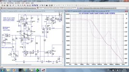
This uses the same compensation principle as in my "200W CFA MOSFET" or "Unique" amps, and I call it Output Inclusive Two Pole compensation (OITCP).
The main advantage over TMC I used in this TT amp is much better Gain marine, hence better stability.
--------------------------TMC------------- OITCP
THD20k at 100W/8---- 1.91 ppm------- 1.64 ppm
THD1k at 100W/8----- 0.03 ppm------- 0.02 ppm
ULGF-------------------- 2.26 MHz------- 3.6 MHz
PM---------------------- 63 degree------- 69 degree
GM---------------------- 9 dB------------- 23 dB
BR Damir
Attachments
Can you add a link to this (new) sch into post1?
The link added.
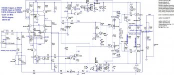
This is in some way simplified and in the same time enhanced version of this TT amp.
It has increased open loop bandwidth (Groner fig. 55, comment on Self book) and less GNFB, exceptional PSRR(R33 and C12 connected to the ground) and very low THD.
It has increased open loop bandwidth (Groner fig. 55, comment on Self book) and less GNFB, exceptional PSRR(R33 and C12 connected to the ground) and very low THD.
Attachments
This is in some way simplified and in the same time enhanced version of this TT amp.
Hi Damir
Nice to see your continued work.
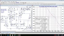
I think you need to move the Tian probe to accurately see the Return Ratio around the OPS.
It needs to be from the OPS before the link (R23) to the intermediate section.
R23 is fairly hi impedance so it may not make much difference but may as well be correct.
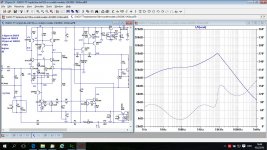
But I still haven't worked out the other loops, I don't understand what the last plot is?
Best wishes
David
Last edited:
Hi Damir
Nice to see your continued work.
I think you need to move the Tian probe to accurately see the Return Ratio around the OPS.
It needs to be from the OPS before the link (R23) to the intermediate section.
R23 is fairly hi impedance so it may not make much difference but may as well be correct.
But I still haven't worked out the other loops, I don't understand what the last plot is?
Best wishes
David
Hi David,
I am all the time doing somethig with audio, just a bit less now when there is more work around house. I haven't seen you around lastly here.
I don't think moving Tian probe will show some difference, but I will try it, just next days I have a tablet only with me.
Best wishes to you too
Damir
...just a bit less now when there is more work around house. I haven't seen you around lastly here.
I have also been busy with work around house but still audio, mostly work on a <1 Part Per Million Distortion oscillator in the Test and Equipment sub-forum.
That kind of Super Low Distortion is not so easy, I have had to think about new ideas.
If you read the thread then I would welcome your comments.
... Tian probe will show some difference, but I will try it, just next days
I think you are correct, the difference should be very small as the circuit now is, but better to have the probe where it should be, then no surprises if you start to modify.
Also people who copy your circuit can learn the correct technique, they may
not be so experienced as you to know when it does or doesn't matter
.Finally, perhaps we are mistaken, sometimes your complicated feedback has not behaved as I initially expected, very educational to understand why.
Best wishes
David
Last edited:
- Status
- This old topic is closed. If you want to reopen this topic, contact a moderator using the "Report Post" button.
- Home
- Amplifiers
- Solid State
- ThermalTrak+TMC amp