Peter Daniel said:I don't see a problem with wiring only 3 fets with the other 3 soldered directly to the board.
As to the gate resistors, I'm not sure. It may depend on the length of the wires: if they are not too long, leaving them on board should work fine too, I guess.
I think the wires shall be about 1 inch long.
They work...
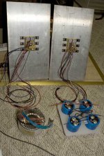
Just fired my A30s up tonight, and they worked great right away.
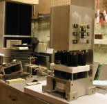
Heatsinks are surplus (WWII from the looks of them) 9"x18" x 2.25" x 22 fins turned sideways because I just like the way it looks, and weren't really much warmer than the room (80F) after 15 minutes of operation.
Rail voltage is 23.89Vdc, which seems low given the 400VA 20V Antek transformer. 80mVACrms ripple in each of the power supply rails with a total of 278,000uF capacitance. Why so much? To quote Nelson, "That's what I had on the shelf." Two bridges. CRC with R=.235Ohm. These get hot so I think I'll add more .47Ohms in parallel. Three CL-60 NTC thermistors per Nelson's later split rail designs. Single star ground that *everything* connects to.
FETs are 9610s and IRFP240s purchased in matched sets from the "The Company Store" guy.
No noticeable turn-on or turn-off thumps. Someone please tell Adcom that popping just ain't right...
60mV offset voltage between the + and - spkr terminals.
No hum, but then again, I probably wouldn't notice...
On the scope they appear to clip at 15.014VACrms into a 6.89 Ohm resistive load, or 32.7-ish Watts.
I have 25 year old speakers, a tin ear and a very loud window unit AC in my apartment, so critical listening is mostly out of the question. but it sounds great to me!
Overall I'm extremely pleased at how easy it was to get this amp running. This is my first DIY amp, and I'm very pleased at the ease of construction. The only thing that went wrong was a failure to electrically isolate the two diff pair transistor tabs, and this wasn't catastrophic - they just sent +25V to the speaker outputs until I fixed this. Thanks again to everyone who worked to make this possible.
Now to finish the chassis. Does cardboard catch fire at 60C???
Bryan Thompson
bryan@batee.com
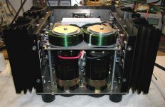
Just fired my A30s up tonight, and they worked great right away.
Heatsinks are surplus (WWII from the looks of them) 9"x18" x 2.25" x 22 fins turned sideways because I just like the way it looks, and weren't really much warmer than the room (80F) after 15 minutes of operation.
Rail voltage is 23.89Vdc, which seems low given the 400VA 20V Antek transformer. 80mVACrms ripple in each of the power supply rails with a total of 278,000uF capacitance. Why so much? To quote Nelson, "That's what I had on the shelf." Two bridges. CRC with R=.235Ohm. These get hot so I think I'll add more .47Ohms in parallel. Three CL-60 NTC thermistors per Nelson's later split rail designs. Single star ground that *everything* connects to.
FETs are 9610s and IRFP240s purchased in matched sets from the "The Company Store" guy.
No noticeable turn-on or turn-off thumps. Someone please tell Adcom that popping just ain't right...
60mV offset voltage between the + and - spkr terminals.
No hum, but then again, I probably wouldn't notice...
On the scope they appear to clip at 15.014VACrms into a 6.89 Ohm resistive load, or 32.7-ish Watts.
I have 25 year old speakers, a tin ear and a very loud window unit AC in my apartment, so critical listening is mostly out of the question.
but it sounds great to me!Overall I'm extremely pleased at how easy it was to get this amp running. This is my first DIY amp, and I'm very pleased at the ease of construction. The only thing that went wrong was a failure to electrically isolate the two diff pair transistor tabs, and this wasn't catastrophic - they just sent +25V to the speaker outputs until I fixed this. Thanks again to everyone who worked to make this possible.
Now to finish the chassis. Does cardboard catch fire at 60C???
Bryan Thompson
bryan@batee.com
Attachments
If you have one channel built and properly heatsinked, just hook it up and measure the rail voltage.
If you don't have the boards built yet, just choose a resistor that will cause 4A to flow (around 6 - 6.5 Ohms). Place it between the power supply rail and ground and measure. Note that it will need to handle 100W.
Or use Nelson's trick of using lightbulbs as power resistors. 24 100W bulbs in parallel should do it...")
Bryan
If you don't have the boards built yet, just choose a resistor that will cause 4A to flow (around 6 - 6.5 Ohms). Place it between the power supply rail and ground and measure. Note that it will need to handle 100W.
Or use Nelson's trick of using lightbulbs as power resistors. 24 100W bulbs in parallel should do it...
Bryan
Banned
Joined 2002
Re: They work...
NO but it gets really warm. Are you using hot glue to tack it all together LOL.. For now i would just elevate the heat sinks like how they are now but up about 1" so air can pass through the bottom of the heat sinks then mount it to a piece of plywood for now..
J'
batee said:Just fired my A30s up tonight, and they worked great right away.
Heatsinks are surplus (WWII from the looks of them) 9"x18" x 2.25" x 22 fins turned sideways because I just like the way it looks, and weren't really much warmer than the room (80F) after 15 minutes of operation.
Rail voltage is 23.89Vdc, which seems low given the 400VA 20V Antek transformer. 80mVACrms ripple in each of the power supply rails with a total of 278,000uF capacitance. Why so much? To quote Nelson, "That's what I had on the shelf." Two bridges. CRC with R=.235Ohm. These get hot so I think I'll add more .47Ohms in parallel. Three CL-60 NTC thermistors per Nelson's later split rail designs. Single star ground that *everything* connects to.
FETs are 9610s and IRFP240s purchased in matched sets from the "The Company Store" guy.
No noticeable turn-on or turn-off thumps. Someone please tell Adcom that popping just ain't right...
60mV offset voltage between the + and - spkr terminals.
No hum, but then again, I probably wouldn't notice...
On the scope they appear to clip at 15.014VACrms into a 6.89 Ohm resistive load, or 32.7-ish Watts.
I have 25 year old speakers, a tin ear and a very loud window unit AC in my apartment, so critical listening is mostly out of the question.
Overall I'm extremely pleased at how easy it was to get this amp running. This is my first DIY amp, and I'm very pleased at the ease of construction. The only thing that went wrong was a failure to electrically isolate the two diff pair transistor tabs, and this wasn't catastrophic - they just sent +25V to the speaker outputs until I fixed this. Thanks again to everyone who worked to make this possible.
Now to finish the chassis. Does cardboard catch fire at 60C???
Bryan Thompson
bryan@batee.com
NO but it gets really warm. Are you using hot glue to tack it all together
LOL.. For now i would just elevate the heat sinks like how they are now but up about 1" so air can pass through the bottom of the heat sinks then mount it to a piece of plywood for now..J'
Banned
Joined 2002
batee said:I was kidding about cardboard, but I think maybe I'll mock up front and rear and top/bottom panels out of pressboard just to make sure I like the arrangement.
That'll get the amp up and running two weeks earlier, too.
Bryan
I know you were joking, i was just pulling the chain
..Are the jumpers show in http://www.diyaudio.com/forums/showthread.php?postid=617068#post617068, necessary?
Thank you,
Peter
Thank you,
Peter
Thanks, Peter!
6 hrs ago, I first applied power to my boards, but it showed that it was drawing more than 2 amps with a short somewhere. Checked once, twice and felt dumb. Never thought of those jumpers, but Peter you saved the day!.
Now both channels are up and running, I will post some pictures later.
Regard,
Peter
cviller said:Any particular reason for R31 being connected to gate of Q10 or is it just a minor bug?
It is a minor bug, but thanks for pointing that out. It's 4:30 AM here so I may not be as sharp as usually
The size is small, but that layout worked successfuly with A30 so it should work fine with F4 as well.
Peter Daniel said:
It is a minor bug......
Hi Peter,
It also looks like you forgot to connect the - of C3 to the junction of R7 and R5.
Marcel.
Tarasque said:It also looks like you forgot to connect the - of C3 to the junction of R7 and R5.
Yes indeed, thanks.
Now, I got another idea. Each of those boards can be also used for Aleph X output, while another small board for input circuitry could be added.
That creates a set of 3 boards, with a total size of 2.4 x 8.2 separated with scoring lines, good for one channel of Aleph X or two channels of F4.
Another good thing about board similarity, is that they are easily interchangable. So anybody who has A30, can now just swap boards and have F4 in a same chassis (only the voltage from transformer may need to adjusted). Not extra holes need to be drilled.
I as well will be still using the same chassis.
http://www.diyaudio.com/forums/showthread.php?postid=613190#post613190
Attachments
Peter,
I am very pleased with making the f4 the same foot print ,I am building an A30 on a similar heat sink . I was going to buy some copper blanks to move boards around on it but this will negate the need, thanks. My current A30 has A 600 kva 18V transformer with 4 47,000 uf capacitors and 2 2mh coils (14 gauge) they are running (the chokes) 70 degrees C. Do you think this is to hot?
I am very pleased with making the f4 the same foot print ,I am building an A30 on a similar heat sink . I was going to buy some copper blanks to move boards around on it but this will negate the need, thanks. My current A30 has A 600 kva 18V transformer with 4 47,000 uf capacitors and 2 2mh coils (14 gauge) they are running (the chokes) 70 degrees C. Do you think this is to hot?
Attachments
- Status
- This old topic is closed. If you want to reopen this topic, contact a moderator using the "Report Post" button.
- Home
- Amplifiers
- Pass Labs
- The Aleph30 PCB layout