it really doesn't matter where some beer money is spent- in your or mine or anyone else's workshop
I do prefer it consumed in my workshop, however 😉
BrianDonegan said:
I do prefer it consumed in my workshop, however 😉
and that's the goal-funnnnnnnnnnnnnn

Sorry for interrupting the discussion. Do the output transistors have to be electrically insulated from the heatsink? I have been looking for insulating kit for the TO-247 package for IRFP240, but with no luck.
Does anyone have a source for the insulating kit, if its necessary?
Thanks,
Peter
Does anyone have a source for the insulating kit, if its necessary?
Thanks,
Peter
peterpan188 said:Sorry for interrupting the discussion. Do the output transistors have to be electrically insulated from the heatsink? I have been looking for insulating kit for the TO-247 package for IRFP240, but with no luck.
Does anyone have a source for the insulating kit, if its necessary?
You should not feel sorry by asking a legitimate questions. Sorry should be the other guy by jumping thread uninvited and trying to make one man bad but pretending himself to be good.
As to your question, yes, the devices need to be insulated, as they carry opposite voltage on their cases. Also, the board is designed in such a way that input differential pair mosfets are in contact, so insulating them from one another is also required.
I've been using TO-220 aluminum oxide pads from Mouser with great results.
Peter Daniel said:
You should not feel sorry by asking a legitimate questions. Sorry should be the other guy by jumping thread uninvited and trying to make one man bad but pretending himself to be good.
As to your question, yes, the devices need to be insulated, as they carry opposite voltage on their cases. Also, the board is designed in such a way that input differential pair mosfets are in contact, so insulating them from one another is also required.
I've been using TO-220 aluminum oxide pads from Mouser with great results.
Peter,
I do have some TO-220 insulating kit from Mouser, with part number 532-4880. But is that big enough for TO-247 package? Does the aluminum oxide pad provide better thermal conductivity?
Thanks,
Peter
If you check the pics here: http://www.diyaudio.com/forums/showthread.php?postid=613623#post613623 you will see that I also used them in my A30 and they worked great. Slightly smaller size is not a problem.
There are certain advantages to using those, but I don't remember exactly what it was. For me, it's mainly convenience 😉
There are certain advantages to using those, but I don't remember exactly what it was. For me, it's mainly convenience 😉
Peter,
I did some more homework on Mouser, and I found an aluminum oxide heatsink pad for TO-218 and TO-247 package, part number 532-4180. That looks like the perfect thing available.
P.S. When I saw aluminum oxide, for a second there, I thought its electrical conductive....
Thanks,
Peter
I did some more homework on Mouser, and I found an aluminum oxide heatsink pad for TO-218 and TO-247 package, part number 532-4180. That looks like the perfect thing available.
P.S. When I saw aluminum oxide, for a second there, I thought its electrical conductive....
Thanks,
Peter

silpad
Digikey also has the silpad isolator for the to-247 "heatpad";sp900, part no. ber178-nd, .87 each. .009 thick.
Digikey also has the silpad isolator for the to-247 "heatpad";sp900, part no. ber178-nd, .87 each. .009 thick.
Just finished my Aleph 30s (using Peters boards).
Thanks again to Nelson for sharing his designs with us, and to Peter for his hard work developing the boards.
When I fired up my amps initially, I got +25Vdc between the + and - speaker terminals.
Some checking revealed that while the diff pair needs to be coupled thermally, they still need to be insulated from each other electrically. This wasn't initially obvious to me. I considered it, then looked at the board and saw a trace connecting a pin on one FET to the same pin on the other FET, so I assumed this was the same as was connected to the FET tabs and screwed both of the tabs to my diff pair heatsink (isolated from both the chassis gnd and the drains on the 240 FETs).
I checked the datasheet and found that the case tabs are connected to the FET drains, and the schematic shows the sources tied together, so I disconnected the diff pair FET tabs from one another and the amp began functioning as expected (34W into a 6.8 Ohm resistor before clipping).
My only idea for solving this problem is to use a pair of Silpads for TO-220s and a pair of those plastic insulators to isolate the screw from both of the tabs. Does anyone have ideas for thermally coupling the diff pair and heatsinking the diff pair without having the drains electrically connected?
Thanks!
Bryan A. Thompson
bryan@batee.com
Peter Daniel said:certain advantages to using those
Two of them are that the risk of conductivity after mounting device and insulator is reduced to almost zero, and not a chance of puncturing them.
A few manufacturers nowadays use multilayer PCBs with Al2O2 insulator pads integrated on/into the boards.
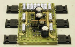
Might as well post an output stage example picture, this one is mounted directly to a stainless steel bottom=>
Attachments
C7 Value?
Hi guys, all my components just arrived from various source, but unfortunately, I found a mistake that I made.
For C7, which supposed to be a 1nF or 0.001uF film capacitor, I order a 10nF in the same Panasonic series. As I see it, C7 is a compensation cap for Q5, so is this value critical? What kind of loss am I facing if I go ahead and use this 10nF?
Thanks,
Peter
You don't really need to use that cap at all, I didn't. And if you still need 1nF, I can send you some.
Thank you for your kind offer, Peter.
I do have access to some 1nF film caps, I was just wondering if I really need to be precise here, because I kind of want to justify my mistake, or may be I can use the component I spent money on
I probably will leave it out for now, and put in the 10nF for some testhing, and see if anything changes. Did Papa say anything about the value of this cap?
Thanks again,
Peter
peterpan188 said:I probably will leave it out for now, and put in the 10nF for some testhing, and see if anything changes. Did Papa say anything about the value of this cap?
IIRC, he mentioned that in Aleph X that cap was omitted due to improved layout, but I can't be sure.
My memory is not too good on this, but I think I recall NP saying that if that cap is too big it will effect freq. response, and that you only really need it if it oscillates.
Don't bank on that though...
edit: It wasn't NP that replied to me... it was Wuffwaff , here:
http://www.diyaudio.com/forums/showthread.php?s=&postid=579183&highlight=#post579183
Don't bank on that though...
edit: It wasn't NP that replied to me... it was Wuffwaff , here:
http://www.diyaudio.com/forums/showthread.php?s=&postid=579183&highlight=#post579183
Here it is, on those caps in XA amp: http://www.diyaudio.com/forums/showthread.php?postid=66005#post66005
BrianDonegan said:I did something similar here:
An externally hosted image should be here but it was not working when we last tested it.
Maybe,it's a stranges question but are those copper plates need they to be lapped(if this is the right word)?
- Status
- Not open for further replies.
- Home
- Amplifiers
- Pass Labs
- The Aleph30 PCB layout