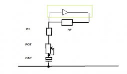
Not in parallel, but like this... although it's just a series chain the pot goes in the "earthy" end to minimise noise pickup. The resistor R1 adds to the resistance of the pot, preventing the gain going far to high. Just use a good quality commercial grade electroylitic.
Attachments
Thanks! I've got some caps on the way from Mouser. I'll give it a try this weekend and see what I get.
Another thing I've had going on regardless of the chip is when I turn the gain all the way up it makes some nasty noises. I'm thinking oscillating but I don't really know how to identify oscillation. Any thoughts?
Another thing I've had going on regardless of the chip is when I turn the gain all the way up it makes some nasty noises. I'm thinking oscillating but I don't really know how to identify oscillation. Any thoughts?
Attachments
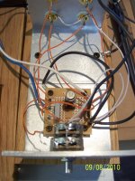
Noises... there's a lot of wiring in there isn't there ")
You say it does it with either opamp.
First... pot's don't like DC current passing through the wiper. That's not an issue with the FET opamp, it is with the bjt though. The cap would stop that. Also just if you wondered, the FET one can still be used with the cap in place for the bjt so you can swap and compare without changing anything.
Is the noise constantly there with the pot at max gain ? or only when the wiper is moving ?
You can short the pot out temporarily to see if the noise stops. That gives max gain.
Also have you got a small cap across the PSU pins of the opamp (4 and 8) ? You should have Something like a 10uf electroylitic... but try anything, even a 0.1uf will stop oscillation.
You say it does it with either opamp.
First... pot's don't like DC current passing through the wiper. That's not an issue with the FET opamp, it is with the bjt though. The cap would stop that. Also just if you wondered, the FET one can still be used with the cap in place for the bjt so you can swap and compare without changing anything.
Is the noise constantly there with the pot at max gain ? or only when the wiper is moving ?
You can short the pot out temporarily to see if the noise stops. That gives max gain.
Also have you got a small cap across the PSU pins of the opamp (4 and 8) ? You should have
Something like a 10uf electroylitic... but try anything, even a 0.1uf will stop oscillation.Yeah that wiring is out of control! Believe it or not the board and the wiring were very tidy for a while. A bunch of experimenting and tracking down grounding issues has made a mess of it. I'm going to rebuild the whole thing when I get it close to right. Probably with a different circuit board that I found.
The noise is always there at max gain.
There are no caps on the PSU pins.
I also included some 0.1uf polyprops in my Mouser order just for that purpose. I was planning to try them this weekend.
So pin 4 to ground and pin 8 to ground?
The noise is always there at max gain.
There are no caps on the PSU pins.
I also included some 0.1uf polyprops in my Mouser order just for that purpose. I was planning to try them this weekend.
So pin 4 to ground and pin 8 to ground?
check the datasheet for details.There are no caps on the PSU pins.
I also included some 0.1uf polyprops in my Mouser order just for that purpose. I was planning to try them this weekend.
So pin 4 to ground and pin 8 to ground?
Thanks Andrew, I've been through the 49720 data sheet many times. Great stuff in there but nothing that I can find about bypass caps.
I did find a tone control circuit and assembled one, It's working but exhibits the same problems as the gain stage. DC in the output and some oscillation when the treble control is at full. I'll give it the same cap treatment as the gain stage and see what I get.
There's also a riaa pre in there that I plan to assemble once I have the other two circuits working properly. Scott
supply decoupling capacitor.
Just had a quick look and I can't see decoupling nor unity gain stable.
But I did see the RIAA with two 47uF on the supply pins.
The gain/phase diagram shows 60degree phase margin @ unity gain (the phase appears upside down so I'm not sure I'm reading it correctly).
Just had a quick look and I can't see decoupling nor unity gain stable.
But I did see the RIAA with two 47uF on the supply pins.
The gain/phase diagram shows 60degree phase margin @ unity gain (the phase appears upside down so I'm not sure I'm reading it correctly).
Last edited:
Just had a quick look and I can't see decoupling nor unity gain stable.
Hi Andrew,
It is unity gain stable... you had me looking... as I'd seen applications where it was used as such.
Anyway the vital words are on the first page of the data sheet buried in the general description.
ss007
Decoupling, is one of the most hotly debated topics around so just a quick overview.
Adding a cap across the supply pins gives the opamp a low impedance supply. That means that the supply is unable to carry high frequency rubbish, and it also means the opamp works correctly and doesn't in itself oscillate.
Adding caps from each supply pin to ground does the same thing but there is the risk of interfering with the clean ground connection.
That's particularly true with all that wiring in use
It's complex subject... and just adding a cap across the opamp will be all that is needed.
I wanted to try out the tone control circuit on page 27 in the 49720 spec sheets. If I use it in this system I'll have a bypass switch so the eq is only in the signal path when needed.
It's working except for the same issues I had with the gain stage.
I'm not sure where to put the the caps to filter the DC.
It's working except for the same issues I had with the gain stage.
I'm not sure where to put the the caps to filter the DC.
Attachments
You need to isolate the problem. The application note circuit should not give a significant DC offset. With the circuit built as shown, and with the input to it correctly grounded (shorted out), swinging the bass and treble pots shouldn't give much change in the DC at the output.
Check this part of the circuit in isolation and note what what the maximum offset is... should only be a millivolt or two I would guess. Try it at all positions of the bass and treble pots.
Check this part of the circuit in isolation and note what what the maximum offset is... should only be a millivolt or two I would guess. Try it at all positions of the bass and treble pots.
Yes you can run two stages (or more) off the zener supply. You can always drop the value of the resistors feeding them a little if needed. If the output (the voltage across the zeners) is lower than the zener voltage when it's all connected up to the opamps then that means the resistors needs lowering a little.
Aim for around 10 to 20 milliamps flowing in the zeners. If you add a 1 ohm in series with each zener you can measure the volt drop across it and calculate the current.
Aim for around 10 to 20 milliamps flowing in the zeners. If you add a 1 ohm in series with each zener you can measure the volt drop across it and calculate the current.
Andrew, I read in another thread that you posted in "Never mix Signal Ground with Power Ground through a common trace/wire".
Going back to the gain circuit. Where would you make the separation between signal and power?
I'm planning to run Rin to signal ground.
The 100uf cap in line with the volume pot to power ground
a wire from signal ground to the main star ground in the gainclone
a wire from power ground to the zener stabilized supply ground.
Can the ground from the zener supply originate from the main star ground in the gainclone?
Attachments
Hi,
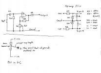
the inputs at the extreme left are:
upper = +IN = signal = hot,
lower = signal ground = signal return.
The signal ground must be connected to the -IN and to the feedback.
This is also where the input filters are terminated.
Bottom right of the diagram shows a horizontal connection from feed back to a pin. Fit a resistor//diode//inverse diode in the line between feedback and pin.
This pin is the Power Ground.
The output Zobel and the Decoupling connect to the Power Ground PIN.
Go and read:
http://www.diyaudio.com/forums/diya...udio-component-grounding-interconnection.html
- Home
- Source & Line
- Analog Line Level
- Simple stereo gain stage