Disconnected blue and white from zener supply.
Zener supply is still hooked to GC supply.
Volume pot reattached.
Ground from zener supply attached to pre amp.
Inputs to pre shorted, outs connected to GC
No hum or noise. Offset at GC out is consistent with no source .073 and .109
Zener supply is still hooked to GC supply.
Volume pot reattached.
Ground from zener supply attached to pre amp.
Inputs to pre shorted, outs connected to GC
No hum or noise. Offset at GC out is consistent with no source .073 and .109
OK...
I don't know what selection of components you have available but can you try adding a resistor in series with both the blue and white supplies to the preamp. Somewhere around 470 ohms... not critical though anywhere from 220 to say 820. They don't have to be equal if you don't have two the same.
Does the noise re appear and if so is it as bad ?
Another option to test would have been to power the preamp from a couple of 9 v batteries just to test... the resistors are easier though and may prove something.
It really needs a 'scope on it to see what is happening.
I had a couple 680 ohm r's.
Same thing at the GC
"It really needs a 'scope on it to see what is happening."
There's a local guy who specializes in classic audio electronics. Maybe it's time to take it to him for a diagnoses. I know it can't be easy figuring out what I screwed up from thousands of miles away. Hopefully he'll be as generous with his knowledge as you fellas. Cheers! I'll post back with his input. Scott
Same thing at the GC
"It really needs a 'scope on it to see what is happening."
There's a local guy who specializes in classic audio electronics. Maybe it's time to take it to him for a diagnoses. I know it can't be easy figuring out what I screwed up from thousands of miles away. Hopefully he'll be as generous with his knowledge as you fellas. Cheers!
I'll post back with his input. ScottWell, I took the circuit in to the local repair guy today. I paid him 50 buck to spend some time with me trying to track down the problem.
He put a scope on it. Now I know what oscillation looks like!
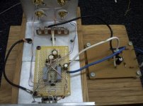
His feelings were that the ground plane really needed attention. He gave me some tips on grounding. I've also been reading a lot about grounding and interconnecting so it made good sense to me.
As you can see in the photo I made a big beefy star grounding junction and brought all the grounds to it. The thick white wire attaches to the center ground bus on the underside of the circuit board.
Minor improvements. Still have major problems.
He also suggested output caps. All I had was some 10uf electrolytics so I put them in series right before the output rca's.
No improvement..
I also tried running the circuit off another +/- 12v supply I have just to break one of the connections to the GC.
No improvement.
I'm not sure if this means anything or not but if I touch either of the two input capacitors on the top I get a ton of weird noises at the speakers.
He put a scope on it. Now I know what oscillation looks like!
His feelings were that the ground plane really needed attention. He gave me some tips on grounding. I've also been reading a lot about grounding and interconnecting so it made good sense to me.
As you can see in the photo I made a big beefy star grounding junction and brought all the grounds to it. The thick white wire attaches to the center ground bus on the underside of the circuit board.
Minor improvements. Still have major problems.
He also suggested output caps. All I had was some 10uf electrolytics so I put them in series right before the output rca's.
No improvement..
I also tried running the circuit off another +/- 12v supply I have just to break one of the connections to the GC.
No improvement.
I'm not sure if this means anything or not but if I touch either of the two input capacitors on the top I get a ton of weird noises at the speakers.
Attachments
It's a steep learning curve isn't it... and I don't really know what to suggest to you with the amp in it's current state. There is some fundamental wiring or construction error for it to do this. There is a lot of fairly lengthy wiring in there too, and also the wiring to the pot (left and right) appears twisted together. That's no good as it introduces capacitive coupling between channels.
Did you try as earlier suggested and disconnect the pot feedback network completely leaving just the feedback resistor around the opamp.
Did you try as earlier suggested and disconnect the pot feedback network completely leaving just the feedback resistor around the opamp.
I've been reading The ESP site and noticed Rod uses a 100 ohm resistor on the output of most of his opamp pre's.
Mooly, you had originally suggested a 680r on the outputs but I decided to leave it off.
It appears that was the problem! I put a 100r on each out and all the problems went away. At least for now We'll see what tomorrow brings.
I'm also going to dump the cat5 cable and use shielded for all the connections.
Mooly, you had originally suggested a 680r on the outputs but I decided to leave it off.
It appears that was the problem! I put a 100r on each out and all the problems went away. At least for now
We'll see what tomorrow brings. I'm also going to dump the cat5 cable and use shielded for all the connections.
That's quite a classic case of instability, and the problem is "worse" with using better opamps with their wider gain/bandwidth. If you used a TL072 it would probably be OK without the resistor.
All you can do is learn from it... and if you are really serious about all this then perhaps think of investing in a 'scope and signal generator.
All you can do is learn from it... and if you are really serious about all this then perhaps think of investing in a 'scope and signal generator.
Excellent... if you search these forums you'll find quite a few threads on 'scopes but what you want is an analogue type with a CRT, not a digital one. Anything over 20mhz bandwidth is ideal for this kind of work and dual trace is worth looking out for.
A signal (or function generator) that does sine and square wave is essential and look at ones that go to at least 100khz.
A signal (or function generator) that does sine and square wave is essential and look at ones that go to at least 100khz.
"That's quite a classic case of instability, and the problem is "worse" with using better opamps with their wider gain/bandwidth. If you used a TL072 it would probably be OK without the resistor."
When an op-amp drives a capacitive load - e.g. a length of shielded cable, or even a real capacitor, a phase shift in the output stage results, and if its large enough, the op amp will oscillate. The lower the closed loop gain of the op-amp stage, the worse the problem is.
For this reason, any op-amp circuit that is going to drive a load that is 'off board', long traces on a PCB or a shielded cable, should have a 50 Ohm 'capacitive load isolation' resistor placed between its output pin and the load. This resistor should be located as close as possible to the output after the feedback resistor.
If you have inserted a 100 Ohm as you indicate above, and the oscillation problem has gone away, the most likely problem is as I described above. Normally, 50 Ohms (47 Ohms) is all that is required, but in cases where you may be driving a heavy capacitve load, higher values might be required - but 100 Ohms really would be th e upper limit.
One other very important point when using op-amps: Make sure that the point where your feedback resistors connect together is right at the inverting input. If the feedback node is located any distance away from the inv input, any noise or RF hash that is picked up along the connection between the resistors and the inv input will be amplified by the full loop gain of the circuit. In a low gain op-amp circuit, this might be 80 or 90dB. Pick up 1uV of hash (easy) and you have 30mV of noise on the output. If your output is driving a capacitve load and there is no isoaltion resistor as described above, the situation will be exacerbated. No amount of power supply decoupling or 'ground planning' will help either.
Can you post up your latest circuit diagram again - lets try to confirm that this is your issue and sort it out.
I haven't been following the whole thread but I had a similar case and found I didn't need the ground on the zener board connected to star ground.
I originally had it laid out as you do and hum!!!!!!.
When I lifted that ground it made everything right.
Don't ask me to explain it as I'm not very technical but I do try different things.
I guess it was creating a loop.
Don't know if you have tried this but just lift that ground from zener supply and see what happens.
If you have already done this I apologize as I didn't go back to page one.
Pol.
that is correct.
Use twisted pairs, or coax, for all 4 signals with their 4 returns.
BUT !!!!!
you must close couple the twisted INPUT pairs and close couple the twisted OUTPUT pairs to minimise the the loop areas in the ground/retrurns.
Similarly, if you use coax you must close couple the screens of the Inputs and the screens of the Outputs to minimise the loop areas.
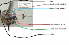
Did you read post46?is this corect conection
Hi, I see that many of you recommended using a 10k pot to attenuate the line level. But, as I understand, the line level spec recommends a resistance between 100 and 600ohm in the line out. Are you really sure a 10k pot will work? Most line input are already 10k that's why the spec says the line out should not be over 600 ohm so it can drive the line input
This is a really old thread now and I can't remember what it was all about but I think you might be confusing output impedance of line stages (which are usually low) and the loading of a 10k pot across that output.
10k is a good starting value for most line level type stages that need a volume control on the output.
and I can't remember what it was all about but I think you might be confusing output impedance of line stages (which are usually low) and the loading of a 10k pot across that output.10k is a good starting value for most line level type stages that need a volume control on the output.
Most that I have seen are 22k even 47k nominal.Most line input are already 10k
A 470r source driving a 10k pot (2.5k @ half gain) driving a 22k input through less than 30 feet of cable is a happy situation.
Much wackier setups "will work".
- Home
- Source & Line
- Analog Line Level
- Simple stereo gain stage