Wow! Thanks! You mean I can just connect the battery to pins 4 & 8 of the TL062 op-amp? So to get a signal level of 5.75 V, I would just need to do this?
Like this Keith, and please start your own separate thread
")
Attachments
I was driving home thinking about this and I realized that originally I was trying to wire the pot in as a variable resistor. I now have the pot on the input. I don't have anything on for R1.
The pot goes "across" the signal source, say the output of the CD player by connecting it to the two end pins. The signal is taken from the middle pin and the input ground... as the pot is turned the wiper moves from ground toward the signal foeming a resistive divider.
That signal is fed to the opamp input.
I'm just looking back... this is why it gets confusing... what diagram are you working too ? Is it the one in post #37 ?
The diagrams I posted the other day and Andrew comments refer to an opamp and "main" volume control... not like in post#37 which was to equalise input levels between sources if I remember correctly.
The diagrams I posted the other day and Andrew comments refer to an opamp and "main" volume control... not like in post#37 which was to equalise input levels between sources if I remember correctly.
I'm just looking back... this is why it gets confusing... what diagram are you working too ? Is it the one in post #37 ?
The diagrams I posted the other day and Andrew comments refer to an opamp and "main" volume control... not like in post#37 which was to equalise input levels between sources if I remember correctly.
Yep, #37 is what i have been working off. I think I'm starting to understand
So the signal ground goes to one end pin on the pot
the signal positive goes to the other end pin on the pot
the center pin on the pot goes to the input on the IC
Yes... but that's for a main volume control. The wiper then allows any value from maximum (the input) through to minimum (ground connection) to be selected... and this signal is then fed to the opamp circuit.
Also if you get the two end connection reversed the pot will work back to front.
Yep, #37 is what i have been working off. I think I'm starting to understand
Lol... that's different.
Here you connect just one end of the pot and the wiper to make the resistance variable, the wiper here doesn't "tap off" the signal... it just makes the value of R1 adjustable.
Doing that alters the gain of the opamp... remember though that the ability to take R1 right down to zero exists at which point the gain of the circuit will increase and increase and ultimately the opamp will latch to one of the rails.
So to stop that add a fixed resistor in series with the pot, say 470 ohms.
Like this Keith, and please start your own separate thread
I will and thank you all! Sorry for the hijack though.
Alright! we're up and runnin, and ROCKIN { Beat Farmers - Tails Of The New West} I might add. Great tip on the series resistor, without it the gain was out of control. I tried a 680r first and the gain was still a bit more than I want. I'll go with 1K for now and see how it goes with the turntable and CD level when I have an input selector wired in.
Am I correct to assume the quality of the pot is not critical to audio sound quality since the signal is not running through it. I've got a Nobel for the main volume before the Gainclone. I don't want to spend another 30 bucks on a high quality pot if it doesn't matter. I was going to upgrade the pot on the phono pre, it looks like the pot is used as a variable feedback resistor. DIY MM Phono Preamplifier Kit (Moving Magnet)
Is that worth upgrading?
I had a couple extra LM833 chips so I did a comparison between the 833 and the opa2604 in the circuit I just built. The 2604 seems fuller to me at first listen. I'm going to get a couple more 2604's and try them in the phono pre.
The feedback signal does pass through the pot... for the non inverting amp (such as the phono preamp) and the one in post #37 the audio signal that appears on pin 2 (- input) is always equal to the applied signal on pin 3. So that signal "passes" or appears across the pot.
By far the best option for the phono stage is to decide in use when the setting is
correct and substitute with a fixed resistor. Big problem of pots is they are big, and prone to pick up stray noise. Worth grounding the out metal part of the pot sometimes (unless it's a plastic one of course).
The LM833 is often thought of as similar to the NE5532.
I've been playing around with this circuit and different op amps. I've decided I want to use the LME49720HA. I'm having problems with DC in the output. With the gain cranked I've got over 1V of DC. You can watch the woofer suck in as I turn the volume up.
I found this great article on op amp problems Working with Cranky Op-Amps and it sounds like I may need to balance my input bias current. I understand the equations he states to do this but I'm not sure how the 25K pot effects all this.
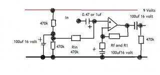
Right now I have a 25K log pot in line with a 1.2K resistor for R1 on the circuit in post #37
RF is 22k and Rin is 470k
Does the 25k pot with the 1.2K resistor make a value of 26.2k for R1?
Any help sorting out this DC problem would be great. Thanks
I found this great article on op amp problems Working with Cranky Op-Amps and it sounds like I may need to balance my input bias current. I understand the equations he states to do this but I'm not sure how the 25K pot effects all this.
Right now I have a 25K log pot in line with a 1.2K resistor for R1 on the circuit in post #37
RF is 22k and Rin is 470k
Does the 25k pot with the 1.2K resistor make a value of 26.2k for R1?
Any help sorting out this DC problem would be great. Thanks
Couple of points.
First you are using a bjt opamp so as the circuit stands what you observe is to be expected. A FET opamp would not do this... that's why I specified them.
To minimise the problem if you want to use the LME then you must AC couple the feedback return, which is the R1. RF and Rin should be equal... which again is a problem if you want to keep Rin at 470K.
Try the cap and see what that brings the offset down too.
The pot and resistor give a maximum of 26.2K and a minimum of 1.2K.
Hi,
many pre-amps and buffers are DC coupled.
Any DC presented to their inputs will be added to any inherent DC in the chip and multiplied by the DC gain of the chip arrangement.
The DC coupled circuit must be designed to ensure that this output offset is controlled.
You need to design the circuit to achieve acceptable output offset if you decide to adopt DC coupled topology.
If you are not yet ready to achieve this design target then delay the adoption of DC coupled until you know enough to design the DC coupled amplifier.
Thanks Mooly and Andrew!
Andrew, I get your point. I've moved on to a Not So Simple Stereo Gain Stage. I built two of these circuits so I think I'll go back to a fet chip on one and put it in use. The other one I think I'll continue to use as my learning tool.
Mooly, I did recognize that you specified a FET op amp and Now I see why. You're right, the opa2604 does not have this problem.
So to Ac couple R1 i use the cap in parallel with the pot/1.3k resistor?
Would you use an electrolytic or a film? --edit-- Just looked at Mouser, doesn't look like films an option for that big of cap. I'll use a Panasonic elec.
Once again thank you two for the time and education. Scott
Last edited:
- Home
- Source & Line
- Analog Line Level
- Simple stereo gain stage