WOW! Thank you for the circuit but more importantly thank you for taking the time to explain things so clearly.
I'm going to spend some time going back through all this info and putting together my plans to make all this happen. I'll have more questions along the way.
Since we are talking about the star ground.... When you say an "offshoot" you mean it should be some distance away? Say 30 mm?
I'm going to spend some time going back through all this info and putting together my plans to make all this happen. I'll have more questions along the way.
Since we are talking about the star ground.... When you say an "offshoot" you mean it should be some distance away? Say 30 mm?
Since we are talking about the star ground.... When you say an "offshoot" you mean it should be some distance away? Say 30 mm?
3 mm, 30, 300 it doesn't matter.
The charging currents that flow in the main caps are in the order of several amps, but with a very short time duration. Under light load the bridge rectifier just "tops off" the charge on the caps. That pulse of current causes a volt drop mirroring those pulse along that centre connection between the two caps.
That drop is easily visible with a 'scope, and it will be of the order of several millivolts "end to end" on the wire.
Why does that matter ?
Because as soon as you connect two grounds there, say an input ground and a feedback return they are not actually at the same potential. A bit of that volt drop is there, because you cannot get down to a single point for all the connections, not even if you wrap all the wire together in a bundle, and that volt drop (the 100/120hz pulses) is amplified and you hear it as hum/buzz.
The offshoot has zero charge current flowing through it, and the end of it becomes our reference point. So the length within reason doesn't matter.
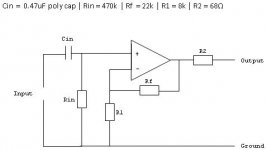
One thing about the OPA2604 and using a pot. As I have shown it the gain is variable over wide limits and as the pot resistance is reduced, the gain increases, with no limit, until at zero resistance, the DC stability of the circuit would be lost and the output would swing to one of the rails, which isn't good practice really.
If you really want a pot on the front panel of the amp it probably makes sense to limit it's action by adding a resistor in series with it so that the minimum resistance of the network is always say 4K7 for example.
Great advice!
This is a great thread to follow along with. I'm kind of a newb with this and I'm learning more here than all the hours I've spent reading different things on the subject. Thanks Scott and Andrew. I'm still not sure how you can power all the circuits with 1 trafo though.
Dan
This is a great thread to follow along with. I'm kind of a newb with this and I'm learning more here than all the hours I've spent reading different things on the subject. Thanks Scott and Andrew. I'm still not sure how you can power all the circuits with 1 trafo though.
Dan
that will leave the volume pot as the last link in the audio signal coming out of the pre-amp.
Most builders would not do that, because the output impedance of a volume pot varies and becomes quite high when volume is set near -6dB (half voltage)
Most builders would not do that, because the output impedance of a volume pot varies and becomes quite high when volume is set near -6dB (half voltage)
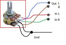
no the output of the opamp goes to the in pin of the volume pot.the IN leads got to the - ins on the opamp?
I think my understanding of this has got me confused.Rf and the pot. I have kept the pot in the "earthy" end of the circuit to minimize stray pickup
How about this.no the output of the opamp goes to the in pin of the volume pot.
The opamp + output goes to the in pin on the pot
The out pin on the pot goes to the + pin on the rca out
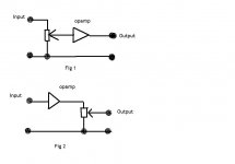
Two main choices,
fig 1 avoids the problem Andrew mentions. The load (your chip amp input) has no effect on the output of the opamp. The downside is that the opamp contributes noise, admitedly this can be very small, and not much more than just the pot on it's own, but there is the real possibility of extra hum and noise due to less than 100% perfect layout/shielding/grounding. Also the opamp needs a fraction of a second to stabilise at power up... and that is passed to the power amp unattenuated. Again not a problem with a foolproof power on delay on the output.
Fig 2 has the drawback that the wiper of the pot is "loaded" by the power amp input. If there's a small capacitance present it forms a low pass filter, the responsr of which alters as the pot is turned. In practice with a 10k pot the effect is minimal, I would have no worries connecting like this with a 10k pot. A 100k pot... no. Also the noise and switch on noises although still present are much attenuated as the control will normally be nowhere near full.
Attachments
Thank you all! Thank you! I've been looking all over for something like this. I want to build an iPod dock [sort of] to connect to my integrated amplifier but want the dock to boost the iPod line out signal level to around 5.75 V from the measly 2.95 V that it currently outputs.
I'm zero [almost] at electronics but understand most of what Mooly was saying/explaining. Now, I do not have existing power to tap into like ss007 did so what do I need to feed power to the op-amp PSU that Mooly drew up?
I'm zero [almost] at electronics but understand most of what Mooly was saying/explaining. Now, I do not have existing power to tap into like ss007 did so what do I need to feed power to the op-amp PSU that Mooly drew up?
Two main choices,
fig 1 avoids the problem Andrew mentions. The load (your chip amp input) has no effect on the output of the opamp. The downside is that the opamp contributes noise, admitedly this can be very small, and not much more than just the pot on it's own, but there is the real possibility of extra hum and noise due to less than 100% perfect layout/shielding/grounding. Also the opamp needs a fraction of a second to stabilise at power up... and that is passed to the power amp unattenuated. Again not a problem with a foolproof power on delay on the output.
Fig 2 has the drawback that the wiper of the pot is "loaded" by the power amp input. If there's a small capacitance present it forms a low pass filter, the responsr of which alters as the pot is turned. In practice with a 10k pot the effect is minimal, I would have no worries connecting like this with a 10k pot. A 100k pot... no. Also the noise and switch on noises although still present are much attenuated as the control will normally be nowhere near full.
Is the feedback resistor used in both these situations?
Is the feedback resistor used in both these situations?
Yes... I just drew a universal amp symbol.
Thank you all! Thank you! I've been looking all over for something like this. I want to build an iPod dock [sort of] to connect to my integrated amplifier but want the dock to boost the iPod line out signal level to around 5.75 V from the measly 2.95 V that it currently outputs.
I'm zero [almost] at electronics but understand most of what Mooly was saying/explaining. Now, I do not have existing power to tap into like ss007 did so what do I need to feed power to the op-amp PSU that Mooly drew up?
Why not use batteries ? Standard CD output is 2 volts RMS... which is just under 6 volts pk/pk. That's do-able off a single 9v battery.
Why not try a super simple project, a dual opamp, single 9 volt battery, and see what you think. Use a really low power consumption opamp like a TLO62, that would give a battery life of a few hundred hours.
If you get stuck perhaps start a new thread off
")
Thanks!
Wow! Thanks! You mean I can just connect the battery to pins 4 & 8 of the TL062 op-amp? So to get a signal level of 5.75 V, I would just need to do this?
Why not use batteries ? Standard CD output is 2 volts RMS... which is just under 6 volts pk/pk. That's do-able off a single 9v battery.
Why not try a super simple project, a dual opamp, single 9 volt battery, and see what you think. Use a really low power consumption opamp like a TLO62, that would give a battery life of a few hundred hours.
If you get stuck perhaps start a new thread off
Wow! Thanks! You mean I can just connect the battery to pins 4 & 8 of the TL062 op-amp? So to get a signal level of 5.75 V, I would just need to do this?
Attachments
No, you need to connect signal ground to a reference about halfway between your + and -.
I'd suggest using two batteries, it keeps things way simpler.
Or, if you really want to use one battery, look at the Cmoy:
HeadWize - Project: A Pocket Headphone Amplifier by Chu Moy
Thousands have built this.
I'd suggest using two batteries, it keeps things way simpler.
Or, if you really want to use one battery, look at the Cmoy:
HeadWize - Project: A Pocket Headphone Amplifier by Chu Moy
Thousands have built this.
Two main choices,
fig 1 avoids the problem Andrew mentions. The load (your chip amp input) has no effect on the output of the opamp. The downside is that the opamp contributes noise, admitedly this can be very small, and not much more than just the pot on it's own, but there is the real possibility of extra hum and noise due to less than 100% perfect layout/shielding/grounding. Also the opamp needs a fraction of a second to stabilise at power up... and that is passed to the power amp unattenuated. Again not a problem with a foolproof power on delay on the output.
Fig 2 has the drawback that the wiper of the pot is "loaded" by the power amp input. If there's a small capacitance present it forms a low pass filter, the responsr of which alters as the pot is turned. In practice with a 10k pot the effect is minimal, I would have no worries connecting like this with a 10k pot. A 100k pot... no. Also the noise and switch on noises although still present are much attenuated as the control will normally be nowhere near full.
Ok, I have it hooked up using figure A so my inputs go through the pot and onto the opamp. It's powered up off the gainclone supply and seems to be working fine. But, the overall output seems a little lower than if I run the mp3 player straight into the gainclone. Do I need a different RF value?
I did have the pot wired up very wrong the first few times I tried the circuit. I heard all kinds of crazy noises and had over the top gain. Maybe I damaged the chip?
Draw what have done with the values... it's difficult just going off descriptions. Picture as well ? That should tell us why the gain is lower.
Unlikely to have damaged the IC... what IC are you using in the end ?
- Home
- Source & Line
- Analog Line Level
- Simple stereo gain stage