Thanks Mikkel for your help for so far.
Getting the answers on your questions, i saw that Q1 (PN2907A) is not in the right position. The device has a metal case that i am not common with. I read the datasheet and saw it.
I will change it and hope this mistake does not had a bad effect on the rest of the equipment.
If changed i try again an come back to this forum (takes a time to get another transistor).
wim said:Getting the answers on your questions, i saw that Q1 (PN2907A) is not in the right position. The device has a metal case that i am not common with. I read the datasheet and saw it.
I will change it and hope this mistake does not had a bad effect on the rest of the equipment.
The transistor should be fine, if you just swapped the emitter and collector pins. It normally works fine when the transistor is installed "backwards" also. Just try installing the transistor the right way and try again - if you can get the transistor out without damaging it of course.
Best regards,
Mikkel C. Simonsen
Mikkel, with the transistor in the right position, no display connected en power on, i measure 5VDC on the input2 and 5VDC on the relvol3, but 0 V between pin 15 and 16 of the displayconnector JP6.
Over R2 (display not connected) i measure 0 V also.
On this displayconnector i measure 5VDC between pin 1 and two and also between the pins 13 and 16 (if inportant).
If i connect the display, 3 things happen: i measure only 2VDC at each point, the regulator gets very hot in about 10 seconds.
Over R2 (display not connected) i measure 0 V also.
On this displayconnector i measure 5VDC between pin 1 and two and also between the pins 13 and 16 (if inportant).
If i connect the display, 3 things happen: i measure only 2VDC at each point, the regulator gets very hot in about 10 seconds.
Mikkel, i have some good news.
I did take another display an connected all the stuff together. Now i measure 5VDC at every point that must hav 5VDC, accept the display backligtpins (15 and 15). They get 0 V, so no backlight.
I powered up one more time, but now with the pushbutton in, and the display (without backlight says: setup running.
Seems to be good, accept the backlicht.
Mayby the transistor is nod good. Is it critical for the system to ignore this failure, cut the wires of pin 15 and 16, and feed the LCD direct? If so, the problem is solved for me.
I hope to hear from you.
Sorry Mikkel, one more time please....
Since i can read the text on the LCD (without backlight) i started the setup procedure and i found that were i had to choose an optie (choose the optie 5 fo RleVol3), that the (smooth) volume encoder did not respond.
After i had finished the setup procedure, i started up the system, and the screen looks normal, but i noticed again that de volume encoder did not give any responce.
The inputselector encoder works fine, i could change inputs and heard the relais clicking.
I checked the cable of the encoders and it seems to be just fine, thats not the problem. Any idee whats wrong? Can it have the same origin as what i told one post afgo: 0 V at pin 15/16 from the display connector?
Thanks again....
wim said:Mikkel, with the transistor in the right position, no display connected en power on, i measure 5VDC on the input2 and 5VDC on the relvol3, but 0 V between pin 15 and 16 of the displayconnector JP6.
Over R2 (display not connected) i measure 0 V also.
On this displayconnector i measure 5VDC between pin 1 and two and also between the pins 13 and 16 (if inportant).
If i connect the display, 3 things happen: i measure only 2VDC at each point, the regulator gets very hot in about 10 seconds.
What type of display have you used? It looks like a display with a two-row connector. If that is the case, the connector is most likely reversed. The connectors on those displays are often mirrored so that pin 1 and 2 is switched, 3 and 4 is switched etc. That will cause problems
") Look for pin numbers on the display PCB.
Look for pin numbers on the display PCB.Also note that the connections on pin 15 and 16 are not part of the standard, so they have to be switched sometimes.
I did take another display an connected all the stuff together. Now i measure 5VDC at every point that must hav 5VDC, accept the display backligtpins (15 and 15). They get 0 V, so no backlight.
If the other display was connected wrongly, I guess you could have killed the transistor. Just try another 2N2907, PN2907 or a BC327 if that's easier to get.
Mayby the transistor is nod good. Is it critical for the system to ignore this failure, cut the wires of pin 15 and 16, and feed the LCD direct? If so, the problem is solved for me.
You can supply the backlight from +5V directly, but you may need a series resistor depending on the display. The backlight will also be on all the time, if it's not switched by the transistor.
Since i can read the text on the LCD (without backlight) i started the setup procedure and i found that were i had to choose an optie (choose the optie 5 fo RleVol3), that the (smooth) volume encoder did not respond.
After i had finished the setup procedure, i started up the system, and the screen looks normal, but i noticed again that de volume encoder did not give any responce.
If you do not (or cannot) select an attenuator type, the volume encoder will not work afterwards, as you have selected an attenuator type with 0 steps
Check the front panel cable for bad connections, shorts and also check if you have swapped the wires on the encoder. There is also a small percentage of the encoders that are out of spec and don't work reliably.
Best regards,
Mikkel C. Simonsen
Mikkel, thenak again for your great help.
At the moment i solved the encoderproblem, did the complete setup again and everything works fine!!
I will change the transistor to get backlight, if that does not solve the problem, i feed the backlight (with serieresistor) direct. Since i will use a on/of switch to give everything power, the backlite will go out also when i turn off the power.
Thanks again for your kind help Mikkel.
I've just discovered that I screwed up the page with "Single voltage supplies" when I updated the website. So I have just received an order for six of these:
And one of these:
I've fixed the page now
Best regards,
Mikkel C. Simonsen
Code:
Item number....: -select-
Description....:  - 26,00 - 150
And one of these:
Code:
Item number....: 5V
Description....:  - 5,00 Õ - 100
I've fixed the page now
Best regards,
Mikkel C. Simonsen
Now I finally have a couple of new kits!
The first is a tube output stage for the CD-Pro2 player. It has a gain of -1, so it "fixes" the inverted output of the CD module. It is powered by the CDPROPSU kit. It could be used for other CD-players/purposes also I guess.
The other kit is an FM stereo (MPX) decoder. It can be used for DIY tuners or for upgrading mono tuners. It will also be a part of a complete tuner eventually. But some parts for the tuner board became obsolete during the design phase, so I have to re-design that...
Both kits can be found under Kits -> Source equipment.
So now I only have about 10 unfinished projects waiting
Best regards,
Mikkel C. Simonsen
Hi Mikkel, could you please confirm if I have all the parts needed before I order - here's what I'd like to order
Control2
C2Panel1-1
RelVol3
(2) resistors for RelVol3
(5V power supply kit)
would I have everything I need to control volume and mute function in a balanced system? If I decided to add input board later, would I need to add anything else aside from (input2) input board (ie, another controller, etc)?
Second setup question - I would like to convert an existing preamp to remote volume control - it currently uses a pot for attenuation. Can I replace it just with the following or would I need more pieces
VolControl1
Relvol1
resistors for RelVol1
5V single supply psu kit
I have also read in other threads that some parts provide soft-start and mute on start (timed) function - is this the input board or volume attenuator board or the control board (does volcontrol provide this?)
Thanks
Stephen
twitchie said:Hi Mikkel, could you please confirm if I have all the parts needed before I order - here's what I'd like to order
Control2
C2Panel1-1
RelVol3
(2) resistors for RelVol3
(5V power supply kit)
I don't have the PCBs for the RelVol3 currently. They will take a week or two to arrive. I guess I should get the website updated today also...
would I have everything I need to control volume and mute function in a balanced system? If I decided to add input board later, would I need to add anything else aside from (input2) input board (ie, another controller, etc)?
Yes, that is all you would need apart from a display.
Second setup question - I would like to convert an existing preamp to remote volume control - it currently uses a pot for attenuation. Can I replace it just with the following or would I need more pieces
VolControl1
Relvol1
resistors for RelVol1
5V single supply psu kit
You could, yes.
I have also read in other threads that some parts provide soft-start and mute on start (timed) function - is this the input board or volume attenuator board or the control board (does volcontrol provide this?)
The mute relay is on the input selector board. The output for controlling a delay relay is on the Control2 board. The VolControl boards will mute (or switch to -63dB) for some seconds on powerup also though.
Best regards,
Mikkel C. Simonsen
Project Complete!
Hi Mikkel,
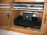
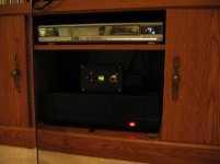
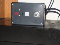
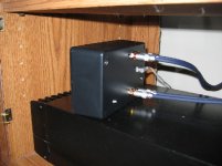
I finished up my passive attenuator project a couple weeks ago, and am finally getting around to posting. This was my first PCB-based project, and everything went very smoothly - largely due to the clear instructions you include. In fact, stuffing the boards was the easy part. Packaging into a Radio Shack project box proved to be more challenging! If I had to do it over, I'd pick a larger box and use more flexible wire. But for now I'm happy to have a working kit with decent aesthetics.
As for the sonics, I won't get carried away, but my wife and I both feel that clarity was improved. This attenuator is replacing a mid-90's Adcom GTP-500 preamp. The Adcom sometimes had a bit of DC offset (small "thump" on ON/OFF) and you could also hear (with your ear up to the speaker) the FM radio bleeding through to the CD output when no CD was playing. This is just to say that the Adcom wasn't a pure pass-through, though I had no other major complaints. So I am not surprised to find improved clarity by removing it from the system. The new attenuator does the job simply, works well, and sounds great.
Anyway, I'll post some pics shortly...
Hi Mikkel,
I finished up my passive attenuator project a couple weeks ago, and am finally getting around to posting. This was my first PCB-based project, and everything went very smoothly - largely due to the clear instructions you include. In fact, stuffing the boards was the easy part. Packaging into a Radio Shack project box proved to be more challenging! If I had to do it over, I'd pick a larger box and use more flexible wire. But for now I'm happy to have a working kit with decent aesthetics.
As for the sonics, I won't get carried away, but my wife and I both feel that clarity was improved. This attenuator is replacing a mid-90's Adcom GTP-500 preamp. The Adcom sometimes had a bit of DC offset (small "thump" on ON/OFF) and you could also hear (with your ear up to the speaker) the FM radio bleeding through to the CD output when no CD was playing. This is just to say that the Adcom wasn't a pure pass-through, though I had no other major complaints. So I am not surprised to find improved clarity by removing it from the system. The new attenuator does the job simply, works well, and sounds great.
Anyway, I'll post some pics shortly...
- Home
- Vendor's Bazaar
- Remote control kits