Go for it. I am starting on mine now too...DaveM said:I would certainly be up for one. I have my f-4 monoblocks up and running and I have been trying to hold out for SY's Impass tube pre, but themay be inevitable.
tms0425 said:Can you describe quick matching procedure/parameters in case I want to get a bucket full of the bulbs myself to play with? How close do they need to be? They show a "sorted" version tested at 1ma, but I imagine it's $$$
I tested/measured resistance of them (resistor part of LDR) in 3 different current points (current through LED part of LDR) ;
say that most convenient points for these bulbs are ....
0,3mA ; 1mA ; 5mA .
that last one - in fact - anything between 5 and 17mA
tip - when you measure all of them , just lined on styrofoam table ( as on some pic up in thread ) , where every one have own No. written by the legs - write down all values in excell ( No. , and all three resistances ) ....... than just sort them in excell file by value of greatest resistance/smallest current through LED part .
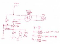
I'll post tomorrow exact schematic ( plain two bjt CCS ) with exact values for current setting resistors .
edit:
here is sketch .
Attachments
Ahhhh, so simple, yet very tedious....
So with 172 devices, you measured and sorted in excel at the 3 currents, grouped to count off by quads (and a few for pairs), so yield is still nearly 100% (other than odd one or two)? In other words the ones within each group of 4 were close enough to each other to work out. No need to worry about absolute values. Nice.
So with 172 devices, you measured and sorted in excel at the 3 currents, grouped to count off by quads (and a few for pairs), so yield is still nearly 100% (other than odd one or two)? In other words the ones within each group of 4 were close enough to each other to work out. No need to worry about absolute values. Nice.
tms0425 said:Ahhhh, so simple, yet very tedious....
So with 172 devices, you measured and sorted in excel at the 3 currents, grouped to count off by quads (and a few for pairs), so yield is still nearly 100% (other than odd one or two)? In other words the ones within each group of 4 were close enough to each other to work out. No need to worry about absolute values. Nice.
you got it
")
just to repeat most important - they're sorted by smallest current/greatest resistance value ;
exactly as you understood - they're all useful , and funny - it's so easy to get mostly quartets .
tms0425 said:That's what I love about this place. Despite being an old guy, I can come here and learn something new every single day thanks to you guys.
Now let's see if Allied will ship me a small bag full of these toys ...
just don't throw them through the window ......... after two dozens

you must measure all of them in one session .
then leave everything for few days , to relax back , sitting apparatus , and brain

jameshillj said:... and then go through the process again with the close ones for better matching - very sensitive to temperature.
naah.......
then just sort them with left hand , behind the back ..........
Maybe I'll test them in the pumpy/shunty case where they'll live so it is nice and toastyjameshillj said:... and then go through the process again with the close ones for better matching - very sensitive to temperature.

Hi Zen Mod,
this weekend i did a big mistake...i´ve build an very easy version
of the lightspeedattenuator a clone of mkII version.
Because i´m curious and impatient i did not match those ldr´s.
Okay...the system is a bit out of balance but the sound is so much
better than any oder volumeregulator...unbelivable.
Now i definitely know I NEED ONE OF THOSE PSMLS-Attenuator-Kits
;-)
Do you know when they will be available?
Greetings Ulf
le´flu said:Hi Zen Mod,
this weekend i did a big mistake...i´ve build an very easy version
of the lightspeedattenuator a clone of mkII version.
Because i´m curious and impatient i did not match those ldr´s.
Okay...the system is a bit out of balance but the sound is so much
better than any oder volumeregulator...unbelivable.
Now i definitely know I NEED ONE OF THOSE PSMLS-Attenuator-Kits
;-)
Do you know when they will be available?
Greetings Ulf
most important thing is that you're satisfied
PSM LS will be available ........ in 2 weeks , I hope .
but - we decided to keep this operation in low volume - to be sure that we aren't in any way troublemakers to GeorgeHiFi production of Lightspeed .
so - batches of LDRs and pcbs will be smaller ( in any case not influencing matching of LDRs ) and final price for package will be somewhat higher .
local boys are thrilled with sound .........
Tea-Bag said:Does this unit act similiar to the original -
optimal performance CD <50 ohms, Amp input >100k?
My CD has 600ohm output trannies...
you need buffers after these xformers ;
not in case that you feed with them 100K pot for tube pre ...... but in case of usual 10K for SS world ......... less trouble is to include buffers than some energy in inadequate energy transfer .
remember - in pro world 600 ohms is input impedance of stage ...... but output imedance of preceding stage must be veeery low .
Zen Mod said:
you need buffers after these xformers ;
not in case that you feed with them 100K pot for tube pre ...... but in case of usual 10K for SS world ......... less trouble is to include buffers than some energy in inadequate energy transfer .
remember - in pro world 600 ohms is input impedance of stage ...... but output imedance of preceding stage must be veeery low .
So lightspeed would be a good thing for impedence into solid state, or did I miss the point?
Maybe some other solution?@Tea-Bag
I was just talking about two different worlds - about so called pro world on one side , and consumer world - on other side ;
first one - pro - where full voltage amplitude is near 1V5 and terminating impedance is 600 Ohms ; there you can find pots ( faders ) anywhere from 1k to 10K .
output impedances of stage(s) were in ohmic values/range
other - rather old consumer world - full voltage were in range of 300-775mV , terminating impedance anywhere between 47K and 330K.
pots were usually in range of 100K and higher .
output impedances were in kiloohmic values/range
today's situation is somewhat mixed - you can buy CD player with output impedance of 1K , same as with output impedance of 50 ohms .
pots are usually in range of 10K to max 47K .
when you have CD player with 1k of output impedance , with 10K pot ..... things are somewhat tricky ....... energy transfer is sorta compromised ....... and then is best to implement most invisible buffer you can find ....
600 ohms - as output impedance of your source - that's on highish side - good for 47K pot .... bit not so nice when using low value pot ....
and unfortunately - LS is on lowish side , so you need decently low impedance to drive it .
Thanks for lengthly explanation.
System does sound good with valve pre @ 50k or direct to tube amp at 100K....
Maybe the Pumpkin with 50K pots will be good. (if I am thinking this applies beyond zero gain devices)
Does B1 suit things better with 50k pot??
Replacing my digital front end or modifying it would be costly. I will need to look for that nearly invisible buffer.
Thanks a lot.
Tea-Bag said:Thanks for lengthly explanation.
System does sound good with valve pre @ 50k or direct to tube amp at 100K....
Maybe the Pumpkin with 50K pots will be good. (if I am thinking this applies beyond zero gain devices)
Does B1 suit things better with 50k pot??
Replacing my digital front end or modifying it would be costly. I will need to look for that nearly invisible buffer.
Thanks a lot.
pot - as a one whole , always have input and output impedance , pretty variable - depending in which position pot exactly is .....
Pumpie is made with 10Ks in input legs ; that's pretty same as input impedance of 10K or 20 K for unbalanced/balanced ;
in case that you want to use 50K pot - my advice will be to increase both input and feedback resistors - in same amount (with decreasing feedback cap )
in fact - these two (per leg ) resistors are both in feedback net ...... but is handy to call them - input and feedback resistor .
B1 - Jfet stage itself is with mountain high input impedance ..... so just any pot is good enough , looking from Jfet side ...... but not for cable/capacity situation .
Papa sez few things about pot value already , but I can tell that you are on safe side if you use anything up to mentioned 50K .
buffers aren't costly ....... especially in case when you really need them .
if you feed toob stage with 100K pot - then you don't need them
le´flu said:Hi there,
so impedance of LS is 10k...am i right?
What inputimpedance of poweramp would you recommend
for the LS?
Cheers ulf
10 K ...... we can say that's ballpark
if you are using just LS ( without buffers) say that 68K-75K of power amp input impedance is lowest you can go .
in case that you are using LS with buffers - you can use as low as 600 ohms inputs
btw - nothing can stop you to implement both outputs on your LS - buffered and non- buffered
Re: PSMLS dedicated buffer - schematic
ZM,
Is above better Option then for drekky 600 ohm out
Uses Jfets it seems. Assuming this is going into production. Maybe not.
Other thought is.
CD---B1----Pumpie---F4--OB Speaker
Maybe too many parts. Maybe ImPass is an idea.
Use Pumpie on Balanced DAC if I can ever make one.
I need to stop bothering you.
Zen Mod said:Buffer - PCB02
schematic - nicely drawn
ZM,
Is above better Option then for drekky 600 ohm out
Uses Jfets it seems. Assuming this is going into production. Maybe not.
Other thought is.
CD---B1----Pumpie---F4--OB Speaker
Maybe too many parts. Maybe ImPass is an idea.
Use Pumpie on Balanced DAC if I can ever make one.
I need to stop bothering you.
Re: Re: PSMLS dedicated buffer - schematic
you need buffer on CD xformer output to ease that signal to reach outer world
you can make it easily - not as B1 , because B1 is pot+buffer , but as sole buffer ...... probably as integrated part od CD alone ;
any kind - either JC , or EB , or whatever .....
you can use Poor Serbian (B1) Buffer - with two J310 ; they're cheap and easy to find .
then you can feed refrigerator , or pot or ..... whatever - when you have low enough output impedance .
which solution you'll use - is completely up to you .
edit :
just a moment - you told that you have 600 ohms output xformers on your CD - but question is - are they already connected in a way that you have ~ 600 ohms output impedance ?
having them ON output is one thing ( as sometime used - as I/V conversion gadgets )
having them connected properly is another thing
give me more informations regarding that .
Tea-Bag said:
ZM,
Is above better Option then for drekky 600 ohm out
Uses Jfets it seems. Assuming this is going into production. Maybe not.
Other thought is.
CD---B1----Pumpie---F4--OB Speaker
Maybe too many parts. Maybe ImPass is an idea.
Use Pumpie on Balanced DAC if I can ever make one.
I need to stop bothering you.
you need buffer on CD xformer output to ease that signal to reach outer world
you can make it easily - not as B1 , because B1 is pot+buffer , but as sole buffer ...... probably as integrated part od CD alone ;
any kind - either JC , or EB , or whatever .....
you can use Poor Serbian (B1) Buffer - with two J310 ; they're cheap and easy to find .
then you can feed refrigerator , or pot or ..... whatever - when you have low enough output impedance .
which solution you'll use - is completely up to you .
edit :
just a moment - you told that you have 600 ohms output xformers on your CD - but question is - are they already connected in a way that you have ~ 600 ohms output impedance ?
having them ON output is one thing ( as sometime used - as I/V conversion gadgets )
having them connected properly is another thing
give me more informations regarding that .
- Home
- Source & Line
- Analog Line Level
- Poor Serbian Man Optical Volume Control