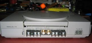
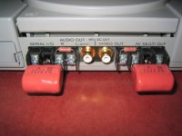
Can some recommend some cap and resistor combo's for a 100k input impedance to my linestage? I plan on using some terminal blocks at the rear of the ps1 to allow me to swap these around and for a later upgrade of better caps. Should have some pics of this soon.
I don't have a problem doing the math on Mick's website
http://dogbreath.de/PS1/output/output.html
I am just not sure what I should be shooting for with the high pass filter going into 100k. I'm dumb in this area but I can solder.
Thanks
I don't have a problem doing the math on Mick's website
http://dogbreath.de/PS1/output/output.html
I am just not sure what I should be shooting for with the high pass filter going into 100k. I'm dumb in this area
but I can solder. Thanks
Hickup
Just wanted to mention the couple of hickups I had along the way.
Right off the bat I messed up before I even started. When I went to remove the power plug for the laser the receptical ripped off the board. Now I see why many have said nice pics Mick because man these parts are small on this board. I never soldered such small componets before. Luckily I was able to solder the receptical back down and think I got it to where it is better than before.
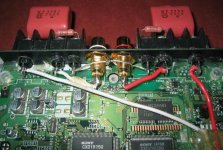
Everything else went as planned and pretty smooth until my last solder joint. I had everything done and couldn't leave well enough alone and decided to add a little more solder to the left channel next to the dac. I think I used to much heat and the pad lifted off the board. Now I know the meaning of in and out, I just left it in too long. Caution to those thinking of performing these mods, this has to be the most delicate part to deal with. It wasn't easy and not sure how I had success at it but I was able to solder a small piece of wire straight to the dac on pin 16 for the left channel and all is good now.
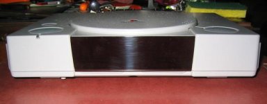
All in all it was a fun project with great benefits and can't wait to get the remote in. I plan on doing something similiar like I did on the back by removing the board from the plug for the controller and memory card slot and putting a blank plate to cover the hole in the front. This way should give plenty of room in front of the ps1 to work with. Also am thinking of mounting everything to the pcb so the cover can be removed without anything fixed to it. When the time comes I will post pics.
Just wanted to mention the couple of hickups I had along the way.
Right off the bat I messed up before I even started. When I went to remove the power plug for the laser the receptical ripped off the board. Now I see why many have said nice pics Mick because man these parts are small on this board. I never soldered such small componets before. Luckily I was able to solder the receptical back down and think I got it to where it is better than before.
Everything else went as planned and pretty smooth until my last solder joint. I had everything done and couldn't leave well enough alone and decided to add a little more solder to the left channel next to the dac. I think I used to much heat and the pad lifted off the board. Now I know the meaning of in and out, I just left it in too long. Caution to those thinking of performing these mods, this has to be the most delicate part to deal with. It wasn't easy and not sure how I had success at it but I was able to solder a small piece of wire straight to the dac on pin 16 for the left channel and all is good now.
All in all it was a fun project with great benefits and can't wait to get the remote in. I plan on doing something similiar like I did on the back by removing the board from the plug for the controller and memory card slot and putting a blank plate to cover the hole in the front. This way should give plenty of room in front of the ps1 to work with. Also am thinking of mounting everything to the pcb so the cover can be removed without anything fixed to it. When the time comes I will post pics.
Re: Hickup
Forgot to mention that I hit the safety switch with my iron when soldering the left channel straight to the dac and messed it up. I had to jam the switch so it always stays on to make things work. Anyone see any problems with leaving this like this or should I look into replacing it?
Forgot to mention that I hit the safety switch with my iron when soldering the left channel straight to the dac and messed it up. I had to jam the switch so it always stays on to make things work. Anyone see any problems with leaving this like this or should I look into replacing it?
Re: Re: Hickup
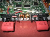
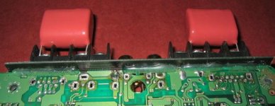
hi ecir38, nice work. A great idea for trying different caps, some of which can be huge.
I did the same to my switch, melted the white block while soldering the caps to the DAC pins. Mine actually still works but I don't think there is any harm in jamming it on. It's only function is to cut the motor when the lid is open, but you'd probably do that anyway via the STOp function on the remote or by the CD stopping at the end of the last track.
ecir38 said:Forgot to mention that I hit the safety switch with my iron when soldering the left channel straight to the dac and messed it up. I had to jam the switch so it always stays on to make things work. Anyone see any problems with leaving this like this or should I look into replacing it?
hi ecir38, nice work. A great idea for trying different caps, some of which can be huge.
I did the same to my switch, melted the white block while soldering the caps to the DAC pins. Mine actually still works but I don't think there is any harm in jamming it on. It's only function is to cut the motor when the lid is open, but you'd probably do that anyway via the STOp function on the remote or by the CD stopping at the end of the last track.
Power Supply Kit in the US?
I'll start by saying I can follow directions and solder. That said i've been looking for a power supply kit that I can buy that leaves me no room to get values wrong. I found this Twisted Pear and beleive it will do the job but i'm not sure.
Any thoughts on what I found?
If not this kit has anyone found something else available from a US supplier?
Thanks in advance for any advice.
Re: Power Supply Kit in the US?
I would be interested to know what others here think too.
I found a link in the achives that should give an idea of the parts used. Note that this looks like an early version and has a differant schematic.
http://web.archive.org/web/20070505133048/http://www.twistedpearaudio.com/
http://web.archive.org/web/20070707081303/twistedpearaudio.com/lcps/lcpskitbom.aspx
Re: Power Supply Kit in the US?
dj_oatmeal, looks like a nice find to me. I am no expert here and since no one else is responding it looks like to me this may be worth a try.
If you notice at that website it has a support section that directs you to their forum. I registered and asked a couple of questions that I had concerns about, check it out.
http://www.twistedpearaudio.com/forum/default.aspx?g=posts&t=185
Thanks for the feedback.
Do you think 15v vs 9v would make that much of a change ot heat output?I'm not much on electronic design but wouldn't changing the transformer require changes to other values in the design?
Looks to me that other than the transformers it would just need an IEC socket,housing,cord to the PS1 and the filter stage that Mick uses to clean the power up. Did I miss anything?
The smallest Avel Lindberg Toroid Transformer is 15VA but they will custom make small quantities at a "reasonable price"
Avel Lindberg
Avel Lindberg
I don't know jack about electrical design either. Saying this I am not sure about the heat that was just a thought. In the link in post 1694 he says the 9v would be ok. Maybe the 15+15 would be the ticket
Hopefully Mick can chime in and give his input on this and the filter stage. Sorry I am not that much help here but I think this looks promissing but hey what do I know.
Don't think we would need anything smaller. 15VA sounds like what we are looking for.
Hopefully Mick can chime in and give his input on this and the filter stage. Sorry I am not that much help here but I think this looks promissing but hey what do I know.
Don't think we would need anything smaller. 15VA sounds like what we are looking for.
- Home
- Source & Line
- Digital Source
- Playstation as CD-player