jake111 said:
which modes will improve the sound?
Hi
While I agree with Mike_F I would add that
that when I changed the output stage of
one of my 1002s I left the laser bias and gain
adjustments alone as the unit was behaving quite
well. After the output conversion I was never
really sure if I liked it as much as the Av out
until I decided to re-adjust the laser bias and
gain, The unit now sounds a lot better and seems
to be breaking in quicker and is more articulate.
Adding spiked feet and a jarrah wood base for me
was the best of all the mods and I am planning
to do the power supply sometime real soon.
I am currently adding gold RCA outputs to a
couple of 5502s and there seems a lot more
room for polypropolene caps in 5502s. I have come
to like the AV section on 5502s with 600/600 ohm
transformers but that may be just a combination
that works with the Denon receiver I have in my
bedroom. So much of the output tweaking depends on
where the signal goes next after the PS1!
I have been offered a rare SCPH5003 at a good price with a
110/240v power supply. I think it is NTSC but I hardly
ever have a display anyway. Good luck with your 1001 mods.
These early PS1 units are very rewarding.It is sad they
cheapened the later units. I hear the Wii is great for games
but has a poor audio section. Pity that skimping on sound quality
is a fact of life for Wii gamers at present.
Regards
AnthonyPT
I agree that the good PS1 sound was likely an accident. I have another theory that appeals to me, even though it probably has little to do with reality. What if, in some obscure Japanese DAC design studio, a programmer was disgusted with the digital sound of DACs at the time and decided to make one that sounded more like analog, more like LPs, even if he had to give up some ultimate accuracy and neutrality? Thanks to whoever it was if he actually existed.
Hi guys!
Well, just when i thoguht it was all over, i moved to uni and plugged my PS1 in (earlier threads lists the mods / other pics)
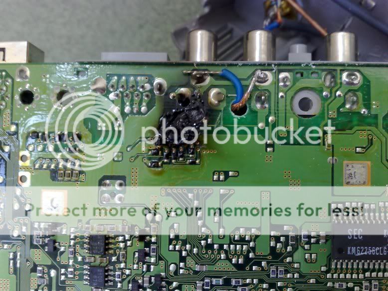
And it started to smoke!
I've had a look inside and this appeared to be the damaged part;
Now, it was tested for approximately 150 hours before I left and all was fine, I dont have a meter with me but the only thing i can think of is that being 150miles away from home, the power system is different and so the voltages I set up in the linear PSU changed?
It was well packed on the way here too!
Any offers to what happened welcome! I have a few more 1002's so can swap parts out (linear psu once checked, IR remote mod etc) , but obviosuly dont want this happeneing again! (I was really lucky not to set off the smoke alarm - wouldnt look good on my 1st day!)
In the mean time im stuck with the rather mediocre output from my soundcard!! Its not nice having something that sounds so good and having to make do!
regards
Dan
Well, just when i thoguht it was all over, i moved to uni and plugged my PS1 in (earlier threads lists the mods / other pics)
And it started to smoke!
I've had a look inside and this appeared to be the damaged part;
Now, it was tested for approximately 150 hours before I left and all was fine, I dont have a meter with me but the only thing i can think of is that being 150miles away from home, the power system is different and so the voltages I set up in the linear PSU changed?
It was well packed on the way here too!
Any offers to what happened welcome! I have a few more 1002's so can swap parts out (linear psu once checked, IR remote mod etc) , but obviosuly dont want this happeneing again! (I was really lucky not to set off the smoke alarm - wouldnt look good on my 1st day!)
In the mean time im stuck with the rather mediocre output from my soundcard!! Its not nice having something that sounds so good and having to make do!
regards
Dan
Hi Dan
Looks terminal for that PU-8 board!
Is the chip on the otherside cooked?
What mod had you done as I do not see any
22k ground resistors on the RCA terminals in the picture
along the lines of the Mike_F mod.
Hope the power supply is still alive?? Any
possibility of a stray piece of wire rocking
around against the shielding during transit?
Something happened to your linear supply in transit
or vibration changed the values?
If you have another motherboard its back to Av
mode for a while.") -(( Hope the laser assembly is alive!
-(( Hope the laser assembly is alive!
Maybe the trace cuts and were marginal or
the removal of Cap on top near RH channel RCA. Hard to know
without seeing the rest of the board clearly.
Check out the voltages on the linear supply and maybe go back to the Old supply until you are sure of the linear one being 100%.
Good luck!
Regards
AnthonyPT
Looks terminal for that PU-8 board!
Is the chip on the otherside cooked?
What mod had you done as I do not see any
22k ground resistors on the RCA terminals in the picture
along the lines of the Mike_F mod.
Hope the power supply is still alive?? Any
possibility of a stray piece of wire rocking
around against the shielding during transit?
Something happened to your linear supply in transit
or vibration changed the values?
If you have another motherboard its back to Av
mode for a while.
-(( Hope the laser assembly is alive!Maybe the trace cuts and were marginal or
the removal of Cap on top near RH channel RCA. Hard to know
without seeing the rest of the board clearly.
Check out the voltages on the linear supply and maybe go back to the Old supply until you are sure of the linear one being 100%.
Good luck!
Regards
AnthonyPT
Hi Audio and Anthony,
The extra wires are there because im using RCA's on the top of the case along with Mundorfs and the 22k's are located there to.
I simply connected both the screen and core to the gnd on the old RCA's and ran this up to the rca's ontop of the case (figured the extra wire was there so might as well use it.
I guess it is a bit confusing to look at it that way without that piece of info.
So basically cut the signal tracks on the old RCA's and used their gnd connection along with the signal coming straight from the chip (i hope that makes sense)
It worked just great so Im confident that part was right.
I might try taking the PSU to one of the labs at uni this week and use their DVM's to check the voltages (the led light still blinks when recieveing IR signal so at least one side is good) - not to sure how the guys there will react though, seeing as its not passed any safety tests etc.
Set up here at uni (active x-over pre amp with 4 X gainclone mono's) was exactly the same as it has been all along.
I'll keep you all posted.
Regards
Dan
Bad luck Dan,
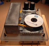
I wonder if the bottom side of the board was shorted on the lower metal plate ? The motherboard is effectively in a metal case, with a thin sheet of metal screening beneath it and the metal fram on which the transport sits above it. Was there any scorching on the lower metal surface beneath the motherboard. I wondered if there was a point of contact between the two causing some arcing ?
I wonder if the bottom side of the board was shorted on the lower metal plate ? The motherboard is effectively in a metal case, with a thin sheet of metal screening beneath it and the metal fram on which the transport sits above it. Was there any scorching on the lower metal surface beneath the motherboard. I wondered if there was a point of contact between the two causing some arcing ?
Hi jives,
There was scorching on the plate (but no obvious pitting from arcing), but at the same time this could just be the residue that was created from the burining pcb.
Had a chat with the lab technicians today and they said they would pat test the psu for me, so theres a start.
I could understand if it was thrown around, but it was wrapped and put in a box and cant imagine it recieved any shocks at all, guess it might just be bad luck!
Regards
Dan
Mick_F said:Just in order to report some new developments from my side: I am now completely circumventing all output circuitry without any replacement. I lead the signal from the DAC directly to new RCAs, which are located on a small metal plate at the position of the parallel port (which I removed). I will show some pics soon on my site. The output has some DC but this is eliminated by a capacitor before the next stage.
I am doing this because I have, in a recent test, noticed that the sound quality strongly depends on the quality of the output capacitors (a well known thing, indeed). However, the capacitors I considered by far the best (among those I tested) are Intertechnik Audyn-cap plus. These capacitors are enormous and will by no way fit into the case of the PS1. Also, this gives me more versatility concerning the choice of components after the PS1 (in particular, to avoid leading the signal through more capacitors than absolutely necessary).
Mick
Mick, have you done this yet? Don't know if I missed it being I am still working through the whole thread.
None in particular. I just think this sounds like the best way to go about this and was hoping to see some pics.
I am new to the CDP scene and am thinking the PS1 will be a fun place to start. Without having and seeing a 1001 yet I do have one question. Why are the existing rca's so difficult to remove? Seems like you could just break it up and desolder one connection at a time then install a new panel across the back. I am thinking I will try this if it is possible if I pick one up.
I am new to the CDP scene and am thinking the PS1 will be a fun place to start. Without having and seeing a 1001 yet I do have one question. Why are the existing rca's so difficult to remove? Seems like you could just break it up and desolder one connection at a time then install a new panel across the back. I am thinking I will try this if it is possible if I pick one up.

- Home
- Source & Line
- Digital Source
- Playstation as CD-player