That's PhaseAccurate (Charles).Someone here wrote a tip about the schottky diode. It must have Cj as low as possible. I´m using a 6pF Cj type (BAT46),
Hi, Blmn,
Try also schottky in D1-D2 (instead of 1n4148), it will speed up the cct a little.
 . But I'm not sure how to configure the values of the L's and C's to get the same 35khz cut filter with Butterworth/Bessel characteristic to 4ohm, like the original UCD paper. Using both 30uH's and 680nF just kills the trebles
Try also schottky in D1-D2 (instead of 1n4148), it will speed up the cct a little.
Fumac used 24dB filter (2L's and 2C's), but the feedback is taken after the first 12dB. The next 12dB is not inclosed in feedback loop. (If you enclosed it, the mosfets will be smoking). I tried this and the output ripple is <0V3 (p-p)Have someone here any experience using third or superior order filter at output?
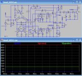
. But I'm not sure how to configure the values of the L's and C's to get the same 35khz cut filter with Butterworth/Bessel characteristic to 4ohm, like the original UCD paper. Using both 30uH's and 680nF just kills the trebles Attachments
Lumanaw,
At http://www.nuhertz.com/download.html, you will find a free software for passive filters till 3rd order (if you buy it allow higher orders).
I think the output ripple would be very good using fumac´s method for 3rd order.
Tks for the tip. I´ll try and tell you the results.
best regards
At http://www.nuhertz.com/download.html, you will find a free software for passive filters till 3rd order (if you buy it allow higher orders).
I think the output ripple would be very good using fumac´s method for 3rd order.
Tks for the tip. I´ll try and tell you the results.
best regards
hello Baldin,
I really interested in looking at your website also I respect your attitude in this forum not so many people respect each other like you.
for you and all the forum I like to ask some dummy question like :
1. Why you use half bridge any benefit in UCD amp ?
2. what the benefit of use lower freq for sub amp
3. in AES paper from Mr Bruno about UCD he suggest to use 4 transisitor for higher power level than 200 watt what your opinion ( cascode, darlington ) ?
thanx for any replies
Hi Rembulan
Thanks for the kind words
1. Halfbridge is the easiest to get to work. A full bridge model is more complex, and you have to strugle with balanced feedback.
If you allow for a more complex design, the benefit of a full bridge is a single sided power supply and no supply pumping. You will probably also have less even order distortion.
2. Lower feq means less loss in the power stage which is good, but on the other hand you'll end up with a much physically larger output filter, and probably more loss in the output coil. Therefore I think a freq of 250 kHz is a good compromise.
3. For higher power you need a 2 transistor bufferstage for each mosfet driver.
Baldin,
I use Spectralab, or Right Mark Audio Analyzer (RMAA 5) Results is same, but spectralab show results in real-time.
RMAA better for measure freq response.
classd_fromru
Thanks, I'll try to make some measurements as soon as I get some more time .... really busy at work at the moment
I have, and it is bad result, switching freq is very low. PhaseAccurate explained this to me (Thanks, Charles). It's like putting 100pf cap from B-C of Q9-Q10.since you guys have mentioned BAT64 ,1N4148.. anyone tried 1N5819 schottky??
1N4148 has 4pf, but what we need is a diode with voltage about 0V3, to give margin about another 0V3 for C-E of Q9-Q10. 1N4148 cannot be applied here.
1n4148 is ok
i use it can upto 800K~1.5MHz
The freq not just base one comp
but also all of them(include pcb)
why hi-freq baseband
if u can driver 1mhz in rightway ,u can driver 600K perfect
if get right way in class-d ,the riple of output is very low just with 2 order filters(one L one Cap or 2 caps)
i have test one of my pcb ,just use 2order, it's just 180mV p2p
60mV rms.
and themax outpower is 150Wrms @6r @830K Fpwm.
lumanauw said:
I have, and it is bad result, switching freq is very low. PhaseAccurate explained this to me (Thanks, Charles). It's like putting 100pf cap from B-C of Q9-Q10.
1N4148 has 4pf, but what we need is a diode with voltage about 0V3, to give margin about another 0V3 for C-E of Q9-Q10. 1N4148 cannot be applied here.
ok.... so you mean a 0.3Volt drop is needed with a lowest diode capacitance? .... I dont know if germanium diodes are applicable here... germaniums (some) have .2V drop???
fumac said:1n4148 is ok
i use it can upto 800K~1.5MHz
The freq not just base one comp
but also all of them(include pcb)
why hi-freq baseband
if u can driver 1mhz in rightway ,u can driver 600K perfect
if get right way in class-d ,the riple of output is very low just with 2 order filters(one L one Cap or 2 caps)
i have test one of my pcb ,just use 2order, it's just 180mV p2p
60mV rms.
and themax outpower is 150Wrms @6r @830K Fpwm.
fumac,
having 2nd order filter/s is NOT UCD anymore
tapping the feedback in between ....RX5 said:
fumac,
having 2nd order filter/s is NOT UCD anymore
not ucd_like: with some diffrent
not selfosc,
do u think
feedback is the nomal tech in amp,
most class-d is base on the same way
and dont trust the sch above, is wrong
,is not my real SCHfumac,
1st of all, my DIY UCD is not EXACTLY like the one posted by philips... although there are some REAL nice tips there that I have added to my diy ucd.....
2nd, my input is differential...
3rd,<<and most important>> I wanted/made my diy to be as close as possible to the UCD180...including the over voltage and overcurrent protection... I can achieve more RMS power output if I had access to HIGH CURRENT /FAST MOSFETS Im not into ordering parts and waiting... I use what I have in hand....but I always see to it that its at spec....
see my avatar, thats my diy UCD... done a few months ago... with some help from the great minds here in the forum... including the inventor himself, Bruno Putzeys....
the scheme I followed was the one posted by classd4sure, w/c was banned for being too well knowing.. peace hehehe
I never posted my updated scheme(posted on forum) for fear someone would make money out of my months experimentation and computer simulation...that would be unfair...
I believe its best -some- would try to experiment and get a FEEL of things.. that would be fun and educational.. and MOSFET blowing too...
cheers,
Raff

1st of all, my DIY UCD is not EXACTLY like the one posted by philips... although there are some REAL nice tips there that I have added to my diy ucd.....
2nd, my input is differential...
3rd,<<and most important>> I wanted/made my diy to be as close as possible to the UCD180...including the over voltage and overcurrent protection... I can achieve more RMS power output if I had access to HIGH CURRENT /FAST MOSFETS
Im not into ordering parts and waiting... I use what I have in hand....but I always see to it that its at spec....see my avatar, thats my diy UCD... done a few months ago... with some help from the great minds here in the forum... including the inventor himself, Bruno Putzeys....
the scheme I followed was the one posted by classd4sure, w/c was banned for being too well knowing..
peace heheheI never posted my updated scheme(posted on forum) for fear someone would make money out of my months experimentation and computer simulation...that would be unfair...
I believe its best -some- would try to experiment and get a FEEL of things.. that would be fun and educational.. and MOSFET blowing too...
cheers,
Raff
i think u r know the ucd well, if well , any body can design his own clas-d amp, not need to copy othersRX5 said:fumac,
1st of all, my DIY UCD is not EXACTLY like the one posted by philips... although there are some REAL nice tips there that I have added to my diy ucd.....
2nd, my input is differential...
3rd,<<and most important>> I wanted/made my diy to be as close as possible to the UCD180...including the over voltage and overcurrent protection... I can achieve more RMS power output if I had access to HIGH CURRENT /FAST MOSFETS
see my avatar, thats my diy UCD... done a few months ago... with some help from the great minds here in the forum... including the inventor himself, Bruno Putzeys....
the scheme I followed was the one posted by classd4sure, w/c was banned for being too well knowing..
I never posted my updated scheme(posted on forum) for fear someone would make money out of my months experimentation and computer simulation...that would be unfair...
I believe its best -some- would try to experiment and get a FEEL of things.. that would be fun and educational.. and MOSFET blowing too...
cheers,
Raff
like u i dont want to make my job just for others to make money
so i cant post the full sch
u can see i have post the simple protection, include speaker and oc.
if i have a right design, the pcb can working at a vot +- 20%
phps, i use the fet with vds=100v, so i set the vol +- 40v,it can be fit anywhere.
i think the right way to make a ov proteck is base on the power.
not on the amp.
btw, if i just use ucd, i have no need to not to post the sch
do u think so.
- Status
- This old topic is closed. If you want to reopen this topic, contact a moderator using the "Report Post" button.
- Home
- Amplifiers
- Class D
- Philips UCD application note