zilog said:I have just tested my UcD and ironed out some of the bugs - it is almost 100% SMD, and uses unbroken ground planes. It operates from +-45V and switches at 500kHz with 27uH/680nF output filter. The OC protection uses Vds-sensing during the active periods, and therefore follows temperature. As of now the amp outputs 20A peak when cold and 12A when very hot, maybe need to get this adjusted some. Residual carrier at the output loaded into 2 ohm is 400mVp-p with no input signal.
hi zilog
")
i'm thinking about to design a simple low loss oc pt,
but the rds is dynamic(like ur said :follows temperature ),
it 's hard to do with it
TESTING£¬ something happening ,time limiteclassd_fromru said:Hi fumac
What results of your new measurements on the new pcb?
sorry for late
stepheno said:Hello fumac,
When are you going to translate your web site in English?
Regards, Stephen
i want to
but i have no time to do that,i have translated one page,but my english is poor, sorry for that. will have an english version .but not now.
from today , i'm going to design about 15 type pcbs for my Customers,
BTW, I will have some pcbs with the top mosfet on the world.
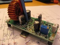
I assembled one of the new PCBs for my mini UcD/Hystersis construction.
It only measures 3.3 x 7.8 cm (almosw only half the size of a credit card).
I have made a small PSU which will power two boards. The PSU has the same PCB size as the amp.
The amp i based on the Philips app note, and some help from here and from classd4sure (same as the breadboard version posted earlier in this thread). Though it is based on the app note, I have made some changes, and left out some components as well.
The construction is intended to run from fairly low voltages, and I'm not sure it will work well for higher powers than around 50W. The idea was to make it small, and I therefore had to make some choises that will limit the powre capability, but not the good sound
Haven't made any real measurements or tried the hysteresis mode yet. I have 4 amp PCBs, so I intend to build two stereo versions and evaluate the difference between pre and post feedback.
More pictures on my homepage:
http://home20.inet.tele.dk/audio/UcD.htm
I was thinking on puting 2 of these amps in a small 2 way speaker construction .... a small active monitor ..... first step taken
Attachments
Hi Baldin,
Wow I congratulate you! its real beautiful mini PCB
Its more little then my mini 20W UcD Now I establish the 2 mini ucds in the 180x160x40mm case with 40w toroid transformer and 2 x 22000/16v caps, sup voltage will be about +- 13v.
Im realy interest to see any measurements (freq response and THD) of you 2 versions (hysteresis anb UcD)
Wow I congratulate you! its real beautiful mini PCB
Its more little then my mini 20W UcD
Now I establish the 2 mini ucds in the 180x160x40mm case with 40w toroid transformer and 2 x 22000/16v caps, sup voltage will be about +- 13v.Im realy interest to see any measurements (freq response and THD) of you 2 versions (hysteresis anb UcD)
Baldin said:I assembled one of the new PCBs for my mini UcD/Hystersis construction.
It only measures 3.3 x 7.8 cm (almosw only half the size of a credit card).
I have made a small PSU which will power two boards. The PSU has the same PCB size as the amp.
The amp i based on the Philips app note, and some help from here and from classd4sure (same as the breadboard version posted earlier in this thread). Though it is based on the app note, I have made some changes, and left out some components as well.
The construction is intended to run from fairly low voltages, and I'm not sure it will work well for higher powers than around 50W. The idea was to make it small, and I therefore had to make some choises that will limit the powre capability, but not the good sound
Haven't made any real measurements or tried the hysteresis mode yet. I have 4 amp PCBs, so I intend to build two stereo versions and evaluate the difference between pre and post feedback.
More pictures on my homepage:
http://home20.inet.tele.dk/audio/UcD.htm
I was thinking on puting 2 of these amps in a small 2 way speaker construction .... a small active monitor ..... first step taken
Baldin,
nice board...
how long does it take (sending it to whoever makes it, and back again to you)??
wish I had done mine too with SMD.. then it would be small...
great minisize
i'm building a mini size one ,include box volume control , oc protect
power frome 220v, and the size is 110mmx110mmx110mm(the box), about 50W RMS "4R, "800¬900k, if some one like ,i can take a picture to show it
i love to build a mini size max power one, to driver my mini speaker and headphone
i'm building a mini size one ,include box volume control , oc protect
power frome 220v, and the size is 110mmx110mmx110mm(the box), about 50W RMS "4R, "800¬900k, if some one like ,i can take a picture to show it
i love to build a mini size max power one, to driver my mini speaker and headphone
Thanks all
classd_fromru
What program are you using for measuring THD?
RX5
I'm using Olimex http://www.olimex.com/pcb/ double sided 160 x 100 mm is 33$ + VAT.
It normally takes 2 weeks from ordering to receiving.
I think it is the sheapest place in the world to handle international orders. You can place different designs on the same panel (as I did here havint 4 amp PCBs and 2 PSUs). Quality is good. ...... try it ...... it's the way to go
lumanauw
It's running a bit higher than 250 kHz. I'm sure it could go higher, but I'll put that off for later.
To get it small and incomplex I skipped the OC protection and some few components like diodes for the input pair gate resistors, snubbers etc. ....... I was also trying to eliminate the current mirror, but that didn't work xeye
fumac
I guess that is with a linear PSU (transformer etc.)?
What I would really like to duo is makng up a SMPS to fit the size.
Anyone want to try that out. Building a 110-240 VAC to 2 x 30 VDC SMPS delivering either 50 or preferably 100 W.
Where would we start? What SMPS chip, that would fit the design, would be easy and cheap to use??
Could we do this as a collective project?
Baldin said:lumanauw
It's running a bit higher than 250 kHz. I'm sure it could go higher, but I'll put that off for later.
To get it small and incomplex I skipped the OC protection
I've built a prototype UCD based on the Philips circuit, and also only runs at about 250KHz -- I can't seem to get it to run higher!
I've taken the opposite approach to you, Baldin! - I didn't need to get the amp as small as possible, and I wanted to try using through hole components. So my prototype PCB is quite a bit bigger than yours!
I also used both OCP, and OVP . I had trouble with the -ve rail pumping and taking out the low side Mosfet , if the output was short circuited with no signal present (i.e. no reason for OCP to operate!). OVP helps there.
I also found that a differential input made a big difference to the amp stability, so I've since added that as well.
I'm wondering if the use of through hole components, together with a bigger PCB, has an influence on the switching frequency. I've tried different components in the lead network, and different values for the output filter, but neither seems to make much difference -- I wonder if the propogation delay is affected much by the PCB layout - more likely the stray capacitance from the larger tracks limiting the lead network minimum capacitance value, I suspect!
I guess I'll have to go SMT if I need to up the switching frequency above 250KHz!
Baldin said:Thanks all
fumac
I guess that is with a linear PSU (transformer etc.)?
What I would really like to duo is makng up a SMPS to fit the size.
Anyone want to try that out. Building a 110-240 VAC to 2 x 30 VDC SMPS delivering either 50 or preferably 100 W.
Where would we start? What SMPS chip, that would fit the design, would be easy and cheap to use??
Could we do this as a collective project?
some body likes pwm power,somebody likes transformer,
so i have two vers on it ,the pwm power up to more high power
i have made 2 simple pwm power one is tl494, is very simple.
after u build a class-d amp,u can very easy to build a pwm power.
BEST RG
FUMAC
rogs said:
I've built a prototype UCD based on the Philips circuit, and also only runs at about 250KHz -- I can't seem to get it to run higher!
I've taken the opposite approach to you, Baldin! - I didn't need to get the amp as small as possible, and I wanted to try using through hole components. So my prototype PCB is quite a bit bigger than yours!
I also used both OCP, and OVP . I had trouble with the -ve rail pumping and taking out the low side Mosfet , if the output was short circuited with no signal present (i.e. no reason for OCP to operate!). OVP helps there.
I also found that a differential input made a big difference to the amp stability, so I've since added that as well.
I'm wondering if the use of through hole components, together with a bigger PCB, has an influence on the switching frequency. I've tried different components in the lead network, and different values for the output filter, but neither seems to make much difference -- I wonder if the propogation delay is affected much by the PCB layout - more likely the stray capacitance from the larger tracks limiting the lead network minimum capacitance value, I suspect!
I guess I'll have to go SMT if I need to up the switching frequency above 250KHz!
Hello Rogs,
I´ve just finished my UcD prototype, trough-hole, and it´s switching at 400kHz (idle), as quoted by Philips UM.
Someone here wrote a tip about the schottky diode. It must have Cj as low as possible. I´m using a 6pF Cj type (BAT46), and the output filter was set to 50kHz.
Kartino has agreat design trough hole too.
Best regards,
blmn said:Someone here wrote a tip about the schottky diode. It must have Cj as low as possible. I´m using a 6pF Cj type (BAT46), and the output filter was set to 50kHz
I'm using BAT 85 for the driver transistor Baker clamps, but 1N4148 everywhere else -- and I've never tried the filter as high as 50KHz -- time for more experiments, I think - thanks for the tips.
rogs and lumanaw,
Actually a filter at 50kHz or more implicates one thing more: an almost flat frequency response until 20kHz.
Have someone here any experience using third or superior order filter at output?
I´m using Schottky´s only in d9 and d10 (from philips UM) and I got 400kHz at idle and 1v pp residual at idle (4ohms load).
dummy question
hello Baldin,
I really interested in looking at your website also I respect your attitude in this forum not so many people respect each other like you.
for you and all the forum I like to ask some dummy question like :
1. Why you use half bridge any benefit in UCD amp ?
2. what the benefit of use lower freq for sub amp
3. in AES paper from Mr Bruno about UCD he suggest to use 4 transisitor for higher power level than 200 watt what your opinion ( cascode, darlington ) ?
thanx for any replies
- Status
- This old topic is closed. If you want to reopen this topic, contact a moderator using the "Report Post" button.
- Home
- Amplifiers
- Class D
- Philips UCD application note