http://www.diyaudio.com/forums/attachment.php?s=&postid=1122825&stamp=1170389808
this pic is ur test pic?
if yes ,the gnd of test is wrong,u must to palce the gnd of test to the speaker output gnd , it will be a right test result on it.
(i dont piont to grow or down, that is just the right point)
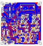
UR pcb I CANT read fine, because it have no companents on it")
this pic is ur test pic?
if yes ,the gnd of test is wrong,u must to palce the gnd of test to the speaker output gnd , it will be a right test result on it.
(i dont piont to grow or down, that is just the right point)
UR pcb I CANT read fine, because it have no companents on it
hi fumac!
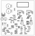
what do you think about my pcb?
(Circuit on my website)
Its based on appnote but out of comparator other.
Can you tell for us values of R & RC in feedback in your circuit, or it same with appnote circuit?
And am interesting values Qg, diode Trr, delaying and on/off time of you mosfets.
what do you think about my pcb?
An externally hosted image should be here but it was not working when we last tested it.
(Circuit on my website)
Its based on appnote but out of comparator other.
Can you tell for us values of R & RC in feedback in your circuit, or it same with appnote circuit?
And am interesting values Qg, diode Trr, delaying and on/off time of you mosfets.
classd_fromru
my friend
i like u design
the pcb is so cool
i think u catch the best of the class-d,
the draw of can work at very hi-speed
but i think the companment is diffrent between us
like :the 47u,i use the dip mode, i have test, that the cap i use is better than the smd i can buy in a good price,and higher-vot.
i cant answer something, u know ,i 'm not only a diyer,but also a biz-man , i'm sorry for that.
by the way ,i'll pose a super simple over current and speaker protect, after i test my new pcb ,
fumac,
thanks!
you say about tantal 47m? its boostrap cap in supply high side driver, it dont need higher than 12v... i can replace it to 100mkf 16v, size is same.
This circuit on hand-made pcb with 28nq15 fets, without input signal always started at 2.5mhz after connect input signal frec. set to 330k and amp work fine on lower freq. i dont know why amp started on 2.5mhz, i dont need it because fets quickly heat up but sound absolutely same with 330k. what do you think about this?
with other fets 540Z 52n15 23n15 amp starting good with 330k...
ps. we will wait you ocp circuit
freq i watch with the scope.
tantal good for hi ripple and hi speed, but standart elcap+ceramic is better i know , i think its not very critical cap in the circuit.
I think my pcb realy good i dont see any ringing in output pulse or low side gate:
but i dont know why THD on 1/2max power only about 0.1- 0.2 %...
tantal good for hi ripple and hi speed, but standart elcap+ceramic is better i know
, i think its not very critical cap in the circuit.I think my pcb realy good
i dont see any ringing in output pulse or low side gate:An externally hosted image should be here but it was not working when we last tested it.
An externally hosted image should be here but it was not working when we last tested it.
but i dont know why THD on 1/2max power only about 0.1- 0.2 %...
An externally hosted image should be here but it was not working when we last tested it.
An externally hosted image should be here but it was not working when we last tested it.
my mcd in 1mhz pwm
An externally hosted image should be here but it was not working when we last tested it.
2
ur dis is Odd dis 1k--3k
my dis is Even dis 1k--2k
i found that the Odd dis is baseon the Comparator
the Even dis is base on dead time
for my self i like a mini Even dis,so i place a jump to control the
Even dis,when i like to i jump it to more dis , this just a personal Interesting
@15w my dis is 0.017%
i'll build a more low dis amp .
wating for new pcb made me cracy
my dis is Even dis 1k--2k
i found that the Odd dis is baseon the Comparator
the Even dis is base on dead time
for my self i like a mini Even dis,so i place a jump to control the
Even dis,when i like to i jump it to more dis ,
this just a personal Interesting@15w my dis is 0.017%
i'll build a more low dis amp .
wating for new pcb made me cracy
classd_fromru said:fumac,
your thd is very good
i trying set very small DT and 2nd harmonic was be higher then 3nd and other.
what diodes in comparator you used, shottky or superfast?
shottky
i read ur picture, i found ur fall time is more than 200ns?
if ture. it's too long to make the low dis
ur can read my pic , 20ns/div,

RX5 said:post some schematics... I like to see one...
whew.. been a while...
RX5
I'LL post the full proteck sch in this link
i must test it before to post
OC proteck and speaker proteck
http://www.diyaudio.com/forums/showthread.php?threadid=94505
my new pcbs come home today
i test it dis=0.2% @6r,150Wrms,1k,pwm=800k,vot=+-50v
i dont know is true or fall ,
because it's 4:20 at night at china, i'm too Tired now ,must go sleep
i will have a full test on it, and post pictures
the simplefull protect have a well done i'll post it ,just 3 Transistor s
bye
i test it dis=0.2% @6r,150Wrms,1k,pwm=800k,vot=+-50v
i dont know is true or fall ,
because it's 4:20 at night at china, i'm too Tired now ,must go sleep
i will have a full test on it, and post pictures
the simplefull protect have a well done i'll post it ,just 3 Transistor s
bye
fumac said:
RX5
I'LL post the full proteck sch in this link
i must test it before to post
OC proteck and speaker proteck
http://www.diyaudio.com/forums/showthread.php?threadid=94505
Not protection circuitry BUT how you manage to come up with osc of 1MHz on your diy ucd...
I have just tested my UcD and ironed out some of the bugs - it is almost 100% SMD, and uses unbroken ground planes. It operates from +-45V and switches at 500kHz with 27uH/680nF output filter. The OC protection uses Vds-sensing during the active periods, and therefore follows temperature. As of now the amp outputs 20A peak when cold and 12A when very hot, maybe need to get this adjusted some. Residual carrier at the output loaded into 2 ohm is 400mVp-p with no input signal.
- Status
- This old topic is closed. If you want to reopen this topic, contact a moderator using the "Report Post" button.
- Home
- Amplifiers
- Class D
- Philips UCD application note