I am far away from my scope (and my prototype is stripped in non-working condition), but I remember somewhere around 1Vp-p sinusoidal residual at the output. I find this ripple through a simple LC filter quite normal, are you sure that the 20mV is not the dc-offset? 1Vp-p at such a high frequency won't induce much power loss at all into a speaker load.
Hi, Zilog,
I get a feeling that the "enemy" of UCD is capacitance. Using groundplane actually makes parasitic capacitance everywhere. But I'm not sure since many people suggest to use groundplane (even the Hypex and UCD modules theirselves uses groundplane).
http://www.diyaudio.com/forums/showthread.php?postid=661854#post661854
How can it be so small? How to achieve it?
Is it possible that infact you dont use ground plane is enabling your UCD to oscilate 500-550khz?and had no ground planes
I get a feeling that the "enemy" of UCD is capacitance. Using groundplane actually makes parasitic capacitance everywhere. But I'm not sure since many people suggest to use groundplane (even the Hypex and UCD modules theirselves uses groundplane).
I read the info here.are you sure that the 20mV is not the dc-offset?
http://www.diyaudio.com/forums/showthread.php?postid=661854#post661854
How can it be so small? How to achieve it?
Hi, Charles,
You are right Using appropriate schottky is crucial, they can make mess.
When I use ordinary schottky (1N5819), I only get 200khz switching with 10V(p-p) sinusoidal at output.
Thanks to your advice, I change the schottky's to BAT54 (capacitance junction = 80pF VS 10pF), I can get 340khz switching and 1V5(p-p) residual.
I think the residual voltage (p-p) and switching frequency are related to each other. The higher switching frequency you get, automaticly the less residual voltage (p-p) at output, at idle.
But using the corelation data that I have so far, I don't think that my UCD can have only 20mV(p-p) if it hits 400khz. How do the real UCD do this, have only 20mV residual?
Do you have other ideas, how to push up the switching frequency? Is it possible that the fact that I use ordinary 1/4watt resistor makes it slower (compared the original SMD resistors)?
Raising the idle current of differential input (lowering 220ohm on ccs) do not effect much.
I wonder what Zilog do (he can achieve 550khz) or even Fumac do (he can achieve 1Mhz)?
You are right
Using appropriate schottky is crucial, they can make mess. When I use ordinary schottky (1N5819), I only get 200khz switching with 10V(p-p) sinusoidal at output.
Thanks to your advice, I change the schottky's to BAT54 (capacitance junction = 80pF VS 10pF), I can get 340khz switching and 1V5(p-p) residual.
I think the residual voltage (p-p) and switching frequency are related to each other. The higher switching frequency you get, automaticly the less residual voltage (p-p) at output, at idle.
But using the corelation data that I have so far, I don't think that my UCD can have only 20mV(p-p) if it hits 400khz. How do the real UCD do this, have only 20mV residual?
Do you have other ideas, how to push up the switching frequency? Is it possible that the fact that I use ordinary 1/4watt resistor makes it slower (compared the original SMD resistors)?
Raising the idle current of differential input (lowering 220ohm on ccs) do not effect much.
I wonder what Zilog do (he can achieve 550khz) or even Fumac do (he can achieve 1Mhz)?
I will report on what switching frequency that I can achieve as soon as I get my new UcD prototype assembled and working, it has unbroken ground planes on 1.55mm thick FR-4, with the modulator board perpendicular to the magnetic fields produced by the output filter, incorporating MMBT3906, FZT790A, BAS81/BAS85 for drivers, all SMD of course. The only thing I can think of that might cause a slow-down even though my last prototype showed no evidence of such, is the addition of resistor-less current sensing of the output mosfets, which loads the main gate drivers by a few percent more than just the FDP3682:s.
lumanauw said:Hi, Charles,
Thanks to your advice, I change the schottky's to BAT54 (capacitance junction = 80pF VS 10pF), I can get 340khz switching and 1V5(p-p) residual.
I think the residual voltage (p-p) and switching frequency are related to each other. The higher switching frequency you get, automaticly the less residual voltage (p-p) at output, at idle.
But using the corelation data that I have so far, I don't think that my UCD can have only 20mV(p-p) if it hits 400khz. How do the real UCD do this, have only 20mV residual?
Do you have other ideas, how to push up the switching frequency? Is it possible that the fact that I use ordinary 1/4watt resistor makes it slower (compared the original SMD resistors)?
Raising the idle current of differential input (lowering 220ohm on ccs) do not effect much.
I wonder what Zilog do (he can achieve 550khz) or even Fumac do (he can achieve 1Mhz)?
i think not to use dip components to make UCD
but u can try to change c23 r29 r32 and l3(base on ur sch mail to me)
the freq of pwm is base on those components
more high freq is base on all the components and PCB
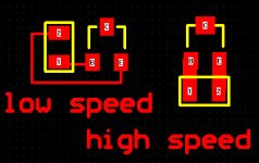
the pcb must be to design it at highspeed mode(i dont know how to say it in english,sorry
)if u can design the PCB base on 50MHZ or higher
it will be group up the PWM freq
we have a new test board on it ,and the most freq is grow up to 2.5MHZ, but hot very fast and the dis is veryhigh, i'm waiting a new FET to fit the FREQ.
1V5(p-p) is not a good job
u can change the L3 OR C42, is not a hard work.
the sch that u send me , it can up to 600K,
try to so with itetc, nice to receiver ur mail
Hi, Fumac,
How can you make 1Mhz, 2.5Mhz, it seems impossible from where I stand right now
1. Do you use schematic DIFFERENT than UCD app note?
2.
How can you make 1Mhz, 2.5Mhz, it seems impossible from where I stand right now
1. Do you use schematic DIFFERENT than UCD app note?
2.
I think I understand what you mean. Where can I read the tutorial about how to draw high speed PCB? Is it different than drawing ordinary PCB?the pcb must be to design it at highspeed mode(i dont know how to say it in english,sorry )
if u can design the PCB base on 50MHZ or higher
it will be group up the PWM freq
lumanauw said:Hi, Fumac,
How can you make 1Mhz, 2.5Mhz, it seems impossible from where I stand right now
1. Do you use schematic DIFFERENT than UCD app note?
2.
I think I understand what you mean. Where can I read the tutorial about how to draw high speed PCB? Is it different than drawing ordinary PCB?
we have 3 versions of class-d amp it's not very hard to drive it up
but u must to really know the SCH
the 3rd verions it not like ucd, not self osc again.
before to made the class-d,i design 900MHZ wireless pruducts , so i draw the pcb of class-d as the 900MHZ
high freq is more DIFFERENT than the nomal , i cant tell u in my poor english, but i can post a pic to let u know it
phase_accurate said:IMO there is absolutely no advantage to go higher than 400 kHz with the switching frequency.
One advantage of a higher switching frequency is that a higher filter cutoff frequency can be used. That basically translates to the use of smaller inductors (value and physical size).
BWRX said:
One advantage of a higher switching frequency is that a higher filter cutoff frequency can be used. That basically translates to the use of smaller inductors (value and physical size).
NOT JUST
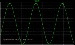
i post 3 pic
1st: Fpwm=350k input sin@20k
2nd Fpwm=470k input sin@20k
3rd: Fpwm=1000k input sin@20k
you can see the diffrent
Attachments
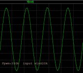
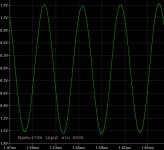
fumac said:u can see 350k cant rebuild the 20k SIN signal
450k rebuild the wrong level
this pic sim by ltspice
350kHz is more than sufficient to properly reproduce a 20kHz signal. Even 250kHz is plenty. You need to provide more details of the circuit you're simulating.
BWRX said:
350kHz is more than sufficient to properly reproduce a 20kHz signal. Even 250kHz is plenty. You need to provide more details of the circuit you're simulating.
if u like u can post ur sim
- Status
- This old topic is closed. If you want to reopen this topic, contact a moderator using the "Report Post" button.
- Home
- Amplifiers
- Class D
- Philips UCD application note